Cisco WS-C2950-24 Hardware Installation Guide - Page 179
Installing the PVDM2 into the PVDM Adapter, Step 4
 |
View all Cisco WS-C2950-24 manuals
Add to My Manuals
Save this manual to your list of manuals |
Page 179 highlights
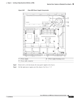
Chapter 5 Installing and Upgrading Internal Modules and FRUs Figure 5-22 Installing the PVDM2 into the PVDM Adapter Installing and Removing PVDM2s 252847 45o Step 4 Step 5 Push the PVDM onto the guide posts. The guide posts should protrude through the guide holes. The connector clips seat themselves on top of the PVDM2, holding the PVDM2 in the adapter. Push both retainer clips over their respective catches. The retainer clips prevent the connector clips from releasing the PVDM2. Figure 5-23 shows the PVDM2 properly installed in the adapter. OL-18712-03 Cisco 2900 Series and 3900 Series Hardware Installation Guide 5-27
-
 1
1 -
2
-
3
-
4
-
5
-
6
-
7
-
8
-
9
-
10
-
11
-
12
-
13
-
14
-
15
-
16
-
17
-
18
-
19
-
20
-
21
-
22
-
23
-
24
-
25
-
26
-
27
-
28
-
29
-
30
-
31
-
32
-
33
-
34
-
35
-
36
-
37
-
38
-
39
-
40
-
41
-
42
-
43
-
44
-
45
-
46
-
47
-
48
-
49
-
50
-
51
-
52
-
53
-
54
-
55
-
56
-
57
-
58
-
59
-
60
-
61
-
62
-
63
-
64
-
65
-
66
-
67
-
68
-
69
-
70
-
71
-
72
-
73
-
74
-
75
-
76
-
77
-
78
-
79
-
80
-
81
-
82
-
83
-
84
-
85
-
86
-
87
-
88
-
89
-
90
-
91
-
92
-
93
-
94
-
95
-
96
-
97
-
98
-
99
-
100
-
101
-
102
-
103
-
104
-
105
-
106
-
107
-
108
-
109
-
110
-
111
-
112
-
113
-
114
-
115
-
116
-
117
-
118
-
119
-
120
-
121
-
122
-
123
-
124
-
125
-
126
-
127
-
128
-
129
-
130
-
131
-
132
-
133
-
134
-
135
-
136
-
137
-
138
-
139
-
140
-
141
-
142
-
143
-
144
-
145
-
146
-
147
-
148
-
149
-
150
-
151
-
152
-
153
-
154
-
155
-
156
-
157
-
158
-
159
-
160
-
161
-
162
-
163
-
164
-
165
-
166
-
167
-
168
-
169
-
170
-
171
-
172
-
173
-
 174
174 -
 175
175 -
 176
176 -
 177
177 -
 178
178 -
 179
179 -
 180
180 -
 181
181 -
 182
182 -
 183
183 -
 184
184 -
185
-
186
-
187
-
188
-
189
-
190
-
191
-
192
-
193
-
194
-
195
-
196
-
197
-
198
-
199
-
200
-
201
-
202
-
203
-
204
-
205
-
206
-
207
-
208
-
209
-
210
-
211
-
212
-
213
-
214
-
215
-
216
-
217
-
218
-
219
-
220
 |
 |

5-27
Cisco 2900 Series and 3900 Series Hardware Installation Guide
OL-18712-03
Chapter 5
Installing and Upgrading Internal Modules and FRUs
Installing and Removing PVDM2s
Figure 5-22
Installing the PVDM2 into the PVDM Adapter
Step 4
Push the PVDM onto the guide posts. The guide posts should protrude through the guide holes. The
connector clips seat themselves on top of the PVDM2, holding the PVDM2 in the adapter.
Step 5
Push both retainer clips over their respective catches. The retainer clips prevent the connector clips from
releasing the PVDM2.
Figure 5-23
shows the PVDM2 properly installed in the adapter.
252847
45
o