Compaq DC7600 HP Compaq dx 7200 and dc7600 Personal Computers, Technical Refer - Page 31
Board Layouts, 9 shows the layout for the USDT systems board - sata layout
 |
UPC - 882780682009
View all Compaq DC7600 manuals
Add to My Manuals
Save this manual to your list of manuals |
Page 31 highlights
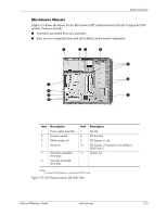
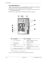
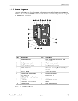
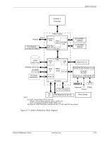
System Overview 2.3.3 Board Layouts Figures 2-11 through 2-13 show the system and expansion boards for these systems. Figure the 2-9 shows the layout for the USDT systems board, which is a custom board specifically designed for that particular form factor. 12 345 6 7 8 p o i 9 u y - t r e wq Item 1 Description Hood sense header 2 Serial port option header 3 Parallel port option header 4 CMOS clear button 5 SATA #0 header 6 Password clear jumper header 7 PCI Express x16 (ADD2/SDVO reversed layout) slot 8 PCI 2.3 slot 9 Power supply (VccP) connector 10 Processor socket Item 11 12 13 14 15 16 17 18 19 20 Description Power button, power LED, HD LED, temp sensor header Chassis speaker connector Front panel audio connector Chassis fan, secondary Front panel USB port connector Chassis fan connector Processor fan connctor DIMM sockets (3) MultiBay riser connector Battery Power supply connector Figure 2-11. USDT System Board Technical Reference Guide www.hp.com 2-15
-
 1
1 -
2
-
3
-
4
-
5
-
6
-
7
-
8
-
9
-
10
-
11
-
12
-
13
-
14
-
15
-
16
-
17
-
18
-
19
-
20
-
21
-
22
-
23
-
24
-
25
-
 26
26 -
 27
27 -
 28
28 -
 29
29 -
 30
30 -
 31
31 -
 32
32 -
 33
33 -
 34
34 -
 35
35 -
 36
36 -
37
-
38
-
39
-
40
-
41
-
42
-
43
-
44
-
45
-
46
-
47
-
48
-
49
-
50
-
51
-
52
-
53
-
54
-
55
-
56
-
57
-
58
-
59
-
60
-
61
-
62
-
63
-
64
-
65
-
66
-
67
-
68
-
69
-
70
-
71
-
72
-
73
-
74
-
75
-
76
-
77
-
78
-
79
-
80
-
81
-
82
-
83
-
84
-
85
-
86
-
87
-
88
-
89
-
90
-
91
-
92
-
93
-
94
-
95
-
96
-
97
-
98
-
99
-
100
-
101
-
102
-
103
-
104
-
105
-
106
-
107
-
108
-
109
-
110
-
111
-
112
-
113
-
114
-
115
-
116
-
117
-
118
-
119
-
120
-
121
-
122
-
123
-
124
-
125
-
126
-
127
-
128
-
129
-
130
-
131
-
132
-
133
-
134
-
135
-
136
-
137
-
138
-
139
-
140
-
141
-
142
-
143
-
144
-
145
-
146
-
147
-
148
-
149
-
150
-
151
-
152
-
153
-
154
-
155
-
156
-
157
-
158
-
159
-
160
-
161
-
162
-
163
-
164
-
165
-
166
-
167
-
168
-
169
-
170
-
171
-
172
-
173
-
174
-
175
-
176
-
177
-
178
-
179
-
180
-
181
-
182
-
183
-
184
-
185
-
186
-
187
-
188
-
189
-
190
-
191
-
192
-
193
-
194
-
195
-
196
-
197
-
198
-
199
-
200
-
201
-
202
-
203
-
204
 |
 |
