Compaq DC7600 HP Compaq dx 7200 and dc7600 Personal Computers, Technical Refer - Page 32
SFF/ST System Board, t - cmos battery
 |
UPC - 882780682009
View all Compaq DC7600 manuals
Add to My Manuals
Save this manual to your list of manuals |
Page 32 highlights
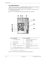
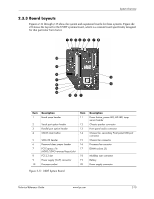
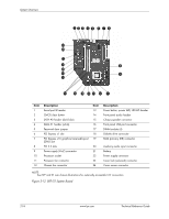
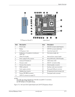
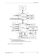
System Overview 123 4 5 6 7 8 f d s a 9 p o - i u y t re w q Item 1 2 3 4 5 6 7 8 9 10 11 12 Description Serial port B header CMOS clear button SATA #0 header (dark blue) SATA #1 header (white) Password clear jumper PCI Express x1 slot PCI Express x16 graphics/reversed-layout SDVO slot PCI 2.3 slots Power supply (VccP) connector Processor socket Processor fan connector Chassis fan conenctor Item 13 14 15 16 17 18 19 20 21 22 23 24 Description Power button, power LED, HD LED header Front panel audio header Chassis speaker connector Front panel USB port connector DIMM sockets (4) Diskette drive connector PATA (primary IDE) connector Auxiliary audio input connector Battery Power supply connector Cover lock (solenoid) connector Cover sensor connector NOTE: See SFF and ST rear chassis illustrations for externally accessible I/O connectors. Figure 2-12. SFF/ST System Board 2-16 www.hp.com Technical Reference Guide
-
 1
1 -
2
-
3
-
4
-
5
-
6
-
7
-
8
-
9
-
10
-
11
-
12
-
13
-
14
-
15
-
16
-
17
-
18
-
19
-
20
-
21
-
22
-
23
-
24
-
25
-
26
-
 27
27 -
 28
28 -
 29
29 -
 30
30 -
 31
31 -
 32
32 -
 33
33 -
 34
34 -
 35
35 -
 36
36 -
 37
37 -
38
-
39
-
40
-
41
-
42
-
43
-
44
-
45
-
46
-
47
-
48
-
49
-
50
-
51
-
52
-
53
-
54
-
55
-
56
-
57
-
58
-
59
-
60
-
61
-
62
-
63
-
64
-
65
-
66
-
67
-
68
-
69
-
70
-
71
-
72
-
73
-
74
-
75
-
76
-
77
-
78
-
79
-
80
-
81
-
82
-
83
-
84
-
85
-
86
-
87
-
88
-
89
-
90
-
91
-
92
-
93
-
94
-
95
-
96
-
97
-
98
-
99
-
100
-
101
-
102
-
103
-
104
-
105
-
106
-
107
-
108
-
109
-
110
-
111
-
112
-
113
-
114
-
115
-
116
-
117
-
118
-
119
-
120
-
121
-
122
-
123
-
124
-
125
-
126
-
127
-
128
-
129
-
130
-
131
-
132
-
133
-
134
-
135
-
136
-
137
-
138
-
139
-
140
-
141
-
142
-
143
-
144
-
145
-
146
-
147
-
148
-
149
-
150
-
151
-
152
-
153
-
154
-
155
-
156
-
157
-
158
-
159
-
160
-
161
-
162
-
163
-
164
-
165
-
166
-
167
-
168
-
169
-
170
-
171
-
172
-
173
-
174
-
175
-
176
-
177
-
178
-
179
-
180
-
181
-
182
-
183
-
184
-
185
-
186
-
187
-
188
-
189
-
190
-
191
-
192
-
193
-
194
-
195
-
196
-
197
-
198
-
199
-
200
-
201
-
202
-
203
-
204
 |
 |
