Compaq DC7600 HP Compaq dx 7200 and dc7600 Personal Computers, Technical Refer - Page 33
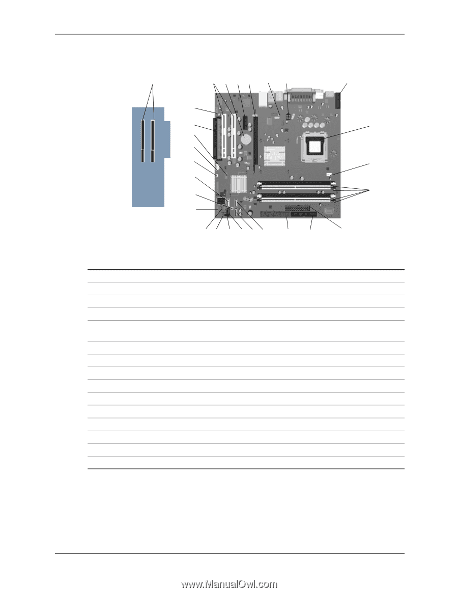
MT and CMT System Board and CMT PCI Expansion Board, f - cmt sata layout
 |
UPC - 882780682009
View all Compaq DC7600 manuals
Add to My Manuals
Save this manual to your list of manuals |
Page 33 highlights
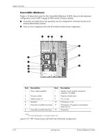
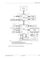
System Overview zk 1 l 1 2 34 5 6 j h g f d s a p oiuytr e w PCI Expansion Board [1] System Board 7 8 9 - q Item 1 2 3 4 5 6 7 8 9 10 11 12 13 14 Description PCI 2.3 slots Battery PCI Express x1 slot PCI Express x16 graphics/normal-layout SDVO slot Chassis fan header Power supply (VccP) connector Serial port B header [2] Processor socket Processor fan connector DIMM sockets (4) Power supply connector Diskette drive connector Primary IDE (PATA) connector SATA #3 connector (orange) [2] Item 15 16 17 18 Description SATA #2 connector (light blue) [2] SATA #0 connector (dark blue) Hood lock header [2] Hood sense header [2] 19 Password clear jumper header 20 Power LED/button, HD LED header 21 CMOS clear switch 22 SATA #1 connector (white) 23 Internal speaker connector 24 Auxiliary audio input connector 25 Front panel USB port connector 26 PCI expansion board connector [2] 27 Front panel audio connector -- -- NOTES: See CMT rear chassis illustration for externally accessible I/O connectors. [1] Applicable to CMT chassis only. [2] Not included on MT system boards. Figure 2-13. MT and CMT System Board and CMT PCI Expansion Board Technical Reference Guide www.hp.com 2-17
-
 1
1 -
2
-
3
-
4
-
5
-
6
-
7
-
8
-
9
-
10
-
11
-
12
-
13
-
14
-
15
-
16
-
17
-
18
-
19
-
20
-
21
-
22
-
23
-
24
-
25
-
26
-
27
-
 28
28 -
 29
29 -
 30
30 -
 31
31 -
 32
32 -
 33
33 -
 34
34 -
 35
35 -
 36
36 -
 37
37 -
 38
38 -
39
-
40
-
41
-
42
-
43
-
44
-
45
-
46
-
47
-
48
-
49
-
50
-
51
-
52
-
53
-
54
-
55
-
56
-
57
-
58
-
59
-
60
-
61
-
62
-
63
-
64
-
65
-
66
-
67
-
68
-
69
-
70
-
71
-
72
-
73
-
74
-
75
-
76
-
77
-
78
-
79
-
80
-
81
-
82
-
83
-
84
-
85
-
86
-
87
-
88
-
89
-
90
-
91
-
92
-
93
-
94
-
95
-
96
-
97
-
98
-
99
-
100
-
101
-
102
-
103
-
104
-
105
-
106
-
107
-
108
-
109
-
110
-
111
-
112
-
113
-
114
-
115
-
116
-
117
-
118
-
119
-
120
-
121
-
122
-
123
-
124
-
125
-
126
-
127
-
128
-
129
-
130
-
131
-
132
-
133
-
134
-
135
-
136
-
137
-
138
-
139
-
140
-
141
-
142
-
143
-
144
-
145
-
146
-
147
-
148
-
149
-
150
-
151
-
152
-
153
-
154
-
155
-
156
-
157
-
158
-
159
-
160
-
161
-
162
-
163
-
164
-
165
-
166
-
167
-
168
-
169
-
170
-
171
-
172
-
173
-
174
-
175
-
176
-
177
-
178
-
179
-
180
-
181
-
182
-
183
-
184
-
185
-
186
-
187
-
188
-
189
-
190
-
191
-
192
-
193
-
194
-
195
-
196
-
197
-
198
-
199
-
200
-
201
-
202
-
203
-
204
 |
 |