Compaq Presario CQ61-400 Compaq Presario CQ61 Notebook PC and HP G61 Notebook - Page 81
RJ-11 (modem) connector (select models only
 |
View all Compaq Presario CQ61-400 manuals
Add to My Manuals
Save this manual to your list of manuals |
Page 81 highlights
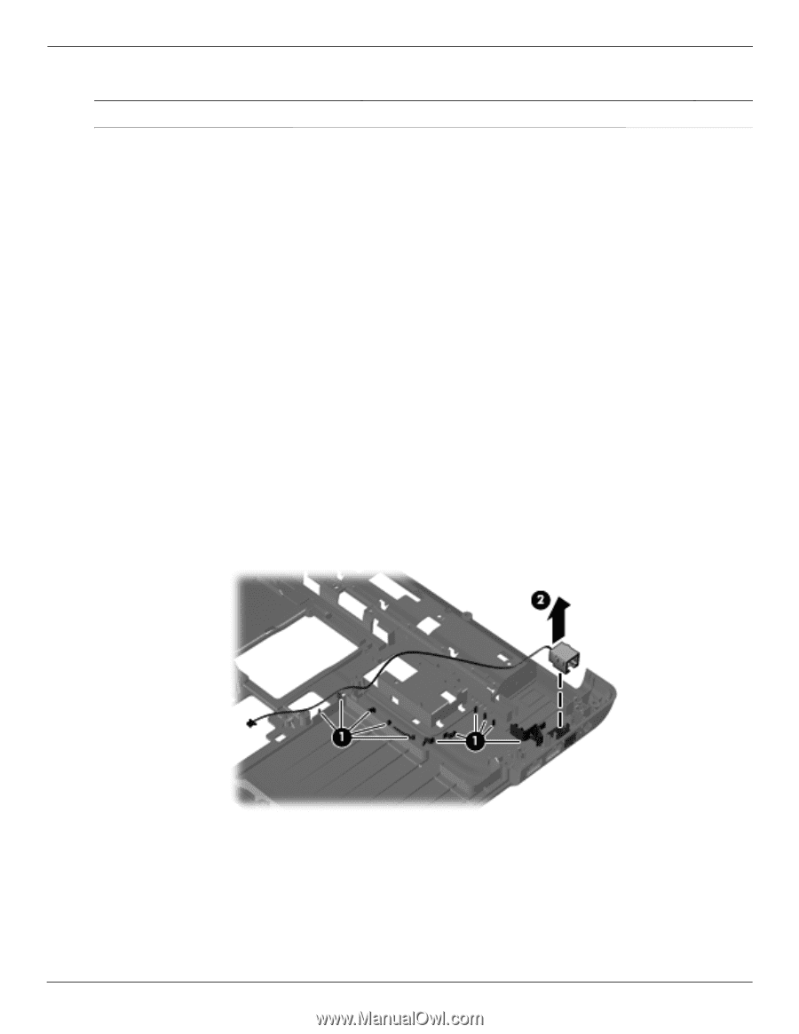
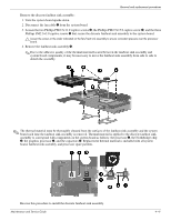
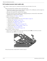
Removal and replacement procedures RJ-11 (modem) connector (select models only) ✎ The RJ-11 (modem) connector is included in the Cable Kit, spare part number 531211-001. Before removing the RJ-11 (modem) connector, follow these steps: 1. Shut down the computer. If you are unsure whether the computer is off or in Hibernation, turn the computer on, and then shut it down through the operating system. 2. Disconnect all external devices connected to the computer. 3. Disconnect the power from the computer by first unplugging the power cord from the AC outlet and then unplugging the AC adapter from the computer. 4. Remove the battery (see "Battery" on page 4-7). 5. Remove the following components: a. Wireless module compartment cover (see "WLAN module" on page 4-8). b. Hard drive (see "Hard drive" on page 4-10). c. Optical drive (see "Optical drive" on page 4-15). d. Keyboard (see "Keyboard" on page 4-16). e. Keyboard cover (see "Keyboard cover" on page 4-18). f. Display assembly (see "Display assembly" on page 4-21). g. Top cover (see "Top cover" on page 4-29). h. System board (see "System board" on page 4-36). Remove the RJ-11 (modem) connector: 1. Remove the RJ-11 (modem) cable from the clips and routing channels 1 built into the base enclosure. 2. Release the connector 2 from its mounting clip. Reverse this procedure to install an RJ-11 (modem) connector. 4-44 Maintenance and Service Guide
-
 1
1 -
2
-
3
-
4
-
5
-
6
-
7
-
8
-
9
-
10
-
11
-
12
-
13
-
14
-
15
-
16
-
17
-
18
-
19
-
20
-
21
-
22
-
23
-
24
-
25
-
26
-
27
-
28
-
29
-
30
-
31
-
32
-
33
-
34
-
35
-
36
-
37
-
38
-
39
-
40
-
41
-
42
-
43
-
44
-
45
-
46
-
47
-
48
-
49
-
50
-
51
-
52
-
53
-
54
-
55
-
56
-
57
-
58
-
59
-
60
-
61
-
62
-
63
-
64
-
65
-
66
-
67
-
68
-
69
-
70
-
71
-
72
-
73
-
74
-
75
-
 76
76 -
 77
77 -
 78
78 -
 79
79 -
 80
80 -
 81
81 -
 82
82 -
 83
83 -
 84
84 -
 85
85 -
 86
86 -
87
-
88
-
89
-
90
-
91
-
92
-
93
-
94
-
95
-
96
-
97
-
98
-
99
-
100
-
101
-
102
-
103
-
104
-
105
-
106
-
107
-
108
-
109
-
110
-
111
-
112
-
113
-
114
-
115
-
116
-
117
-
118
-
119
-
120
-
121
-
122
-
123
-
124
-
125
-
126
-
127
-
128
-
129
-
130
 |
 |