Compaq dx7400 Service Reference Guide - HP Compaq dx7400 Business PC - Page 116
Front I/O Device
 |
View all Compaq dx7400 manuals
Add to My Manuals
Save this manual to your list of manuals |
Page 116 highlights
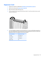
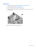
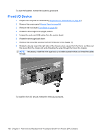
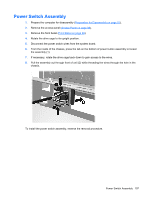
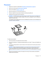
To close the fastener, reverse the loosening procedure. Front I/O Device 1. Prepare the computer for disassembly (Preparation for Disassembly on page 87). 2. Remove the access panel (Access Panel on page 88). 3. Remove the front bezel (Front Bezel on page 89). 4. Rotate the drive cage to its upright position. 5. Unplug the audio and USB cables from the system board. 6. Rotate the drive cage back down. 7. Remove the screw that secures the front I/O device to the chassis (1). 8. Rotate the device toward the right side of the chassis (when viewed from the front), and then pull the device from the chassis (2) while threading the wires through the hole in the chassis. NOTE: If necessary, rotate the drive cage back up to better access the hole you thread the cables through. To install the front I/O device, reverse the removal procedures. 106 Chapter 8 Removal and Replacement Procedures Small Form Factor (SFF) Chassis
-
 1
1 -
2
-
3
-
4
-
5
-
6
-
7
-
8
-
9
-
10
-
11
-
12
-
13
-
14
-
15
-
16
-
17
-
18
-
19
-
20
-
21
-
22
-
23
-
24
-
25
-
26
-
27
-
28
-
29
-
30
-
31
-
32
-
33
-
34
-
35
-
36
-
37
-
38
-
39
-
40
-
41
-
42
-
43
-
44
-
45
-
46
-
47
-
48
-
49
-
50
-
51
-
52
-
53
-
54
-
55
-
56
-
57
-
58
-
59
-
60
-
61
-
62
-
63
-
64
-
65
-
66
-
67
-
68
-
69
-
70
-
71
-
72
-
73
-
74
-
75
-
76
-
77
-
78
-
79
-
80
-
81
-
82
-
83
-
84
-
85
-
86
-
87
-
88
-
89
-
90
-
91
-
92
-
93
-
94
-
95
-
96
-
97
-
98
-
99
-
100
-
101
-
102
-
103
-
104
-
105
-
106
-
107
-
108
-
109
-
110
-
 111
111 -
 112
112 -
 113
113 -
 114
114 -
 115
115 -
 116
116 -
 117
117 -
 118
118 -
 119
119 -
 120
120 -
 121
121 -
122
-
123
-
124
-
125
-
126
-
127
-
128
-
129
-
130
-
131
-
132
-
133
-
134
-
135
-
136
-
137
-
138
-
139
-
140
-
141
-
142
-
143
-
144
-
145
-
146
-
147
-
148
-
149
-
150
-
151
-
152
-
153
-
154
-
155
-
156
-
157
-
158
-
159
-
160
-
161
-
162
-
163
-
164
-
165
-
166
-
167
-
168
-
169
-
170
-
171
-
172
-
173
-
174
-
175
-
176
-
177
-
178
-
179
-
180
-
181
-
182
-
183
-
184
-
185
-
186
-
187
-
188
-
189
-
190
-
191
-
192
-
193
-
194
-
195
-
196
-
197
-
198
-
199
 |
 |