Compaq dx7400 Service Reference Guide - HP Compaq dx7400 Business PC - Page 117
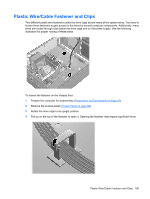
the assembly 1., If necessary, rotate the drive cage back down to gain access to the wires.
 |
View all Compaq dx7400 manuals
Add to My Manuals
Save this manual to your list of manuals |
Page 117 highlights
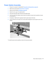
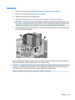
Power Switch Assembly 1. Prepare the computer for disassembly (Preparation for Disassembly on page 87). 2. Remove the access panel (Access Panel on page 88). 3. Remove the front bezel (Front Bezel on page 89). 4. Rotate the drive cage to its upright position. 5. Disconnect the power switch wires from the system board. 6. From the inside of the chassis, press the tab on the bottom of power button assembly to loosen the assembly (1). 7. If necessary, rotate the drive cage back down to gain access to the wires. 8. Pull the assembly out through front of unit (2) while threading the wires through the hole in the chassis. To install the power switch assembly, reverse the removal procedure. Power Switch Assembly 107
-
 1
1 -
2
-
3
-
4
-
5
-
6
-
7
-
8
-
9
-
10
-
11
-
12
-
13
-
14
-
15
-
16
-
17
-
18
-
19
-
20
-
21
-
22
-
23
-
24
-
25
-
26
-
27
-
28
-
29
-
30
-
31
-
32
-
33
-
34
-
35
-
36
-
37
-
38
-
39
-
40
-
41
-
42
-
43
-
44
-
45
-
46
-
47
-
48
-
49
-
50
-
51
-
52
-
53
-
54
-
55
-
56
-
57
-
58
-
59
-
60
-
61
-
62
-
63
-
64
-
65
-
66
-
67
-
68
-
69
-
70
-
71
-
72
-
73
-
74
-
75
-
76
-
77
-
78
-
79
-
80
-
81
-
82
-
83
-
84
-
85
-
86
-
87
-
88
-
89
-
90
-
91
-
92
-
93
-
94
-
95
-
96
-
97
-
98
-
99
-
100
-
101
-
102
-
103
-
104
-
105
-
106
-
107
-
108
-
109
-
110
-
111
-
 112
112 -
 113
113 -
 114
114 -
 115
115 -
 116
116 -
 117
117 -
 118
118 -
 119
119 -
 120
120 -
 121
121 -
 122
122 -
123
-
124
-
125
-
126
-
127
-
128
-
129
-
130
-
131
-
132
-
133
-
134
-
135
-
136
-
137
-
138
-
139
-
140
-
141
-
142
-
143
-
144
-
145
-
146
-
147
-
148
-
149
-
150
-
151
-
152
-
153
-
154
-
155
-
156
-
157
-
158
-
159
-
160
-
161
-
162
-
163
-
164
-
165
-
166
-
167
-
168
-
169
-
170
-
171
-
172
-
173
-
174
-
175
-
176
-
177
-
178
-
179
-
180
-
181
-
182
-
183
-
184
-
185
-
186
-
187
-
188
-
189
-
190
-
191
-
192
-
193
-
194
-
195
-
196
-
197
-
198
-
199
 |
 |

Power Switch Assembly
1.
Prepare the computer for disassembly (
Preparation for Disassembly
on page
87
).
2.
Remove the access panel (
Access Panel
on page
88
).
3.
Remove the front bezel (
Front Bezel
on page
89
).
4.
Rotate the drive cage to its upright position.
5.
Disconnect the power switch wires from the system board.
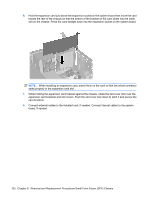
6.
From the inside of the chassis, press the tab on the bottom of power button assembly to loosen
the assembly (1).
7.
If necessary, rotate the drive cage back down to gain access to the wires.
8.
Pull the assembly out through front of unit (2) while threading the wires through the hole in the
chassis.
To install the power switch assembly, reverse the removal procedure.
Power Switch Assembly
107