Compaq dx7400 Service Reference Guide - HP Compaq dx7400 Business PC - Page 123
Preparation for Disassembly, on Access Panel, Expansion Card, Optical Drive, Replacing Memory
 |
View all Compaq dx7400 manuals
Add to My Manuals
Save this manual to your list of manuals |
Page 123 highlights
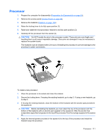
10. Slide the power supply about 1.25 cm (1/2-inch) toward the front of the chassis (2), rotate the power supply toward the heatsink so it clears the lip at the top of the chassis (3), and then lift the power supply out of the chassis (4). To install the system board, reverse the removal procedure. CAUTION: Before reinstalling the heatsink you must clean the top of the processor and the bottom of the heatsink with an alcohol pad supplied in the spares kit. After the alcohol has evaporated, apply thermal grease to the top of the processor from the syringe supplied in the spares kit. NOTE: When reinstalling the system board it is important to secure the system board and tray to the chassis with the long retaining screw before performing any subsequent steps. CAUTION: When reconnecting the cables it is important that they be positioned so they do not interfere with the rotation of the drive cage or power supply. System Board 1. Prepare the computer for disassembly (Preparation for Disassembly on page 87). 2. Remove the access panel (Access Panel on page 88). 3. Remove all PCI and PCI Express expansion boards (Expansion Card on page 101). 4. Remove the optical drive (Optical Drive on page 95). 5. Remove all memory modules (Replacing Memory on page 99). 6. Loosen the plastic cable fastener (Plastic Wire/Cable Fastener and Clips on page 105). 7. Disconnect all data and power cables from the system board. 8. Remove the power supply (Power Supply on page 112). System Board 113
-
 1
1 -
2
-
3
-
4
-
5
-
6
-
7
-
8
-
9
-
10
-
11
-
12
-
13
-
14
-
15
-
16
-
17
-
18
-
19
-
20
-
21
-
22
-
23
-
24
-
25
-
26
-
27
-
28
-
29
-
30
-
31
-
32
-
33
-
34
-
35
-
36
-
37
-
38
-
39
-
40
-
41
-
42
-
43
-
44
-
45
-
46
-
47
-
48
-
49
-
50
-
51
-
52
-
53
-
54
-
55
-
56
-
57
-
58
-
59
-
60
-
61
-
62
-
63
-
64
-
65
-
66
-
67
-
68
-
69
-
70
-
71
-
72
-
73
-
74
-
75
-
76
-
77
-
78
-
79
-
80
-
81
-
82
-
83
-
84
-
85
-
86
-
87
-
88
-
89
-
90
-
91
-
92
-
93
-
94
-
95
-
96
-
97
-
98
-
99
-
100
-
101
-
102
-
103
-
104
-
105
-
106
-
107
-
108
-
109
-
110
-
111
-
112
-
113
-
114
-
115
-
116
-
117
-
 118
118 -
 119
119 -
 120
120 -
 121
121 -
 122
122 -
 123
123 -
 124
124 -
 125
125 -
 126
126 -
 127
127 -
 128
128 -
129
-
130
-
131
-
132
-
133
-
134
-
135
-
136
-
137
-
138
-
139
-
140
-
141
-
142
-
143
-
144
-
145
-
146
-
147
-
148
-
149
-
150
-
151
-
152
-
153
-
154
-
155
-
156
-
157
-
158
-
159
-
160
-
161
-
162
-
163
-
164
-
165
-
166
-
167
-
168
-
169
-
170
-
171
-
172
-
173
-
174
-
175
-
176
-
177
-
178
-
179
-
180
-
181
-
182
-
183
-
184
-
185
-
186
-
187
-
188
-
189
-
190
-
191
-
192
-
193
-
194
-
195
-
196
-
197
-
198
-
199
 |
 |
