Craftsman 536.270320 Owners Manual - Page 21
Howto Checkand Adjust, Clutch - transaxle
 |
View all Craftsman 536.270320 manuals
Add to My Manuals
Save this manual to your list of manuals |
Page 21 highlights
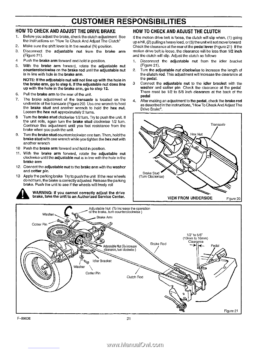
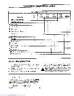
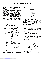
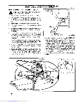
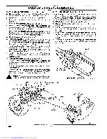
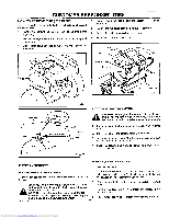
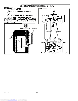
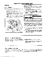
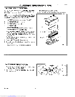
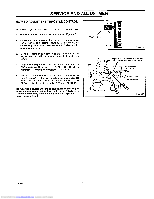
CUSTOMER RESPONSIBILITIES HOW TO CHECK AND ADJUST THE DRIVE BRAKE I. Before you adjust the brake, check the clutch adjustment See the instructions on "How To Check And Adjust The Clutch" 2. Make sure the shift lever is in the neutral (N) position. 3. Disconnect the adjustable nut from the brake arm (Figure 21), 4 Push the brake arm forward and hold in position. 5. With the brake arm forward, rotate the adjustable nut counterclockwise on the brake rod until the adjustable nut is in line with hole in the brake arm. NOTE: If the adjustable nut will not line up with the hole in the brake arm, go to step 6. If the adjustable nut does line up with the hole in the brake arm, go to step 12. 6. Pull the brake arm to the rear of the unit. 7. The brake adjustment of the transaxle is located on the underside of the transaxle (Figure 20) Use one wrench to hold the brake stud and another wrench to hold the hex nut. Loosen the hex nut approximately2 turns. 8 Turn the brake stud clockwise 1/2 turn. Try to push the unit. if the unit roils, again turn the brake stud clockwise 1/2 turn. Continue this adjustment until you feel resistance from the brake when you push the unit. 9. Turn the brake stud countemtockwiseoneturn. Then, holdthe brake stud with one wrench while you tightenthe hex nut with another wrench 10 Push the brake arm forward and hotd in position. 11. With the brake arm forward, rotate the adjustable nut clockwise until the adjustable nut is in line with the hole in the brake arm t 2. Connect the adjustable nut to the brake arm with the washer and cotter pin. 13 Apply the parking brake Try to push the unit If the rear wheels do notturn, the brake iscorrectlyadjusted. Release the parking brake. Push the unit to see if the wheels will freely roll HOWTO CHECKAND ADJUSTTHE CLUTCH If the motion drive belt is loose, the clutch will slip when, (1) going up a hill, (2) pulling a heavy load, or (3) the unit wilt not move forward Check the clearance at the rear of the pedal lever (Figure 21) If the motion drive belt is loose, the clearance wilt be less than 1/2 inch and the clutch will slip. Adjust the clutch as follows I. Disconnect the adjustable nut from the idler bracket (Figure 21). 2. Turn the adjustable nut clockwise to increase the fength of the clutch rod. This adjustment will increase the clearance at the pedal. 3 Connect the adjustable nut to the idler bracket with the washer and cotter pin Check the clearance at the pedal There must be 1/2 to 5/8 inch clearance at the back of the pedal 4. After making an adjustmentto the pedal, check the brake rod as described inthe instructions,"How To Check And Adjust The Drive Brake". _ 4%1 t,,,-_ Transaxle 1 Brake Stud (TurnClockwise) "% i ,_ WbrAaRkeN,INtaGk:e tIhfeyouunitctaonnaontAcuothrroerciztleyd aSdejurvsitcetheCednrtievre. VIEW FROM UNDERSIDE Figure20J Cotter Pin Adjustable Nut (To increase the operation the brake, turn counterc[ockwise ) Brake Arm Nut clearancet,urn clockwis)e Brake Rod 1/2" to 5/8" (13ram to 16ram) Cleat Pedal ]"_ idler Bracket Washer \ Cotter Pin / CtutchRod F-99636 21 Downloaded from www.Manualslib.com manuals search engine Figure 21
-
 1
1 -
2
-
3
-
4
-
5
-
6
-
7
-
8
-
9
-
10
-
11
-
12
-
13
-
14
-
15
-
 16
16 -
 17
17 -
 18
18 -
 19
19 -
 20
20 -
 21
21 -
 22
22 -
 23
23 -
 24
24 -
 25
25 -
 26
26 -
27
-
28
-
29
-
30
-
31
-
32
-
33
-
34
-
35
-
36
-
37
-
38
-
39
-
40
-
41
-
42
-
43
-
44
-
45
-
46
-
47
-
48
-
49
-
50
-
51
-
52
-
53
-
54
-
55
-
56
-
57
-
58
-
59
-
60
 |
 |