Craftsman 536.270320 Owners Manual - Page 28
How To Level The Mower, Housing
 |
View all Craftsman 536.270320 manuals
Add to My Manuals
Save this manual to your list of manuals |
Page 28 highlights
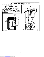
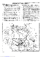
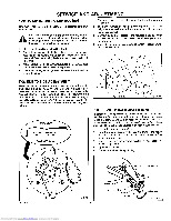
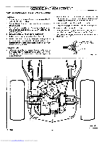
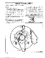
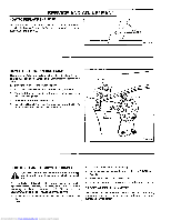
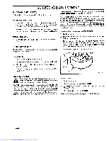
SERVICE AND ADJUSTMENT HOW TO LEVEL THE MOWER HOUSING If the mower housing is level, the blade wiltcut easier and the lawn will look better. WARNING: Before you make an inspection, adjust- _iL mspeanrt,k oprlurgep. aRiremtootvhee tuhneit,spdaisrckonpnluegctwtihree wtoirperteovethnet the engine from starting by accident. 1. Make sure the unit is on a hard level surface 2. Check the air pressure in the tires. If the air pressure is mcorrect, the mower housing will not cut level Make sure the rear tires are inflated to 14 psi. (1 BAR) and the front tires to 22 psi. (1.5 BAR) 3. Move the lever for the attachment clutch to the ENGAGE position Move the lift lever to the middle position 4. There are two adjustment procedures below that will levet the mower housing 1. Disconnect one or both adjuster plates from the hangers (Figure 33) 2. The higher number holes in the adjuster plates will raise the height of the mower housing The lower number holes will lower the mower housing 3. Connect the adjuster plates to the hangers in the holes that will level the mower housing. Fasten the adjuster plates with the hair pins 4. Check the housing for the correct adjustment If necessary, repeat the adjustment \. Hanger THE SIDE TO SIDE ADJUSTMENT There are measuring points on the mower housing indicated by small round dimples A, B, C, and D shown in Figure 32. To determine if an adjustment is needed, use a ruler and measure the distance from the level surface to the bottom of the mower housing at points C and D. in correct adjustment, the mower housing at points C and D must be within 1/4" (6 mm) of the same height If the difference in the measurement is more than 1/4" (6 mm), adjust as follows. SIDE VIEW , _, bottom J.m/ of the mower housing LEVELSURFACE Hair Pin i/// AdjusterPlate Figure 33 THE FRONT TO BACK ADJUSTMENT To determine if an adjustment is needed, use a ruler and measure the distance from the level surface to the bottom of the mower housing at points A and B. In correct adjustment, the front of the mower housing at pointA wiltbe 1/8" to 3/8" (3mm to 9ram) lower than the back of the mower housing at point B. Adjust as follows. 1. Loosen the jam nut (Figure 34). 2. Turn the Iocknut clockwise to raise the front of the mower housing Turn the Iocknut counterclockwiseto lower the front of the mower housing 3 Check the housing for the correct adjustment if necessary, repeat the adjustment 4. Tighten the jam nut 5. Connect the wire to the spark plug. Suspens=on Bracket C F-99636 D Figure 32 28 Suspension Rod Adjusting Clevis Jam Nut Locknut Counterclockwise Figure 34 Downloaded from www.Manualslib.com manuals search engine
-
 1
1 -
2
-
3
-
4
-
5
-
6
-
7
-
8
-
9
-
10
-
11
-
12
-
13
-
14
-
15
-
16
-
17
-
18
-
19
-
20
-
21
-
22
-
 23
23 -
 24
24 -
 25
25 -
 26
26 -
 27
27 -
 28
28 -
 29
29 -
 30
30 -
 31
31 -
 32
32 -
 33
33 -
34
-
35
-
36
-
37
-
38
-
39
-
40
-
41
-
42
-
43
-
44
-
45
-
46
-
47
-
48
-
49
-
50
-
51
-
52
-
53
-
54
-
55
-
56
-
57
-
58
-
59
-
60
 |
 |
