Cub Cadet TANK LZ 60 TANK L 60 KW Operator's Manual - Page 13
Adjusting Drive Control Levers
 |
View all Cub Cadet TANK LZ 60 manuals
Add to My Manuals
Save this manual to your list of manuals |
Page 13 highlights
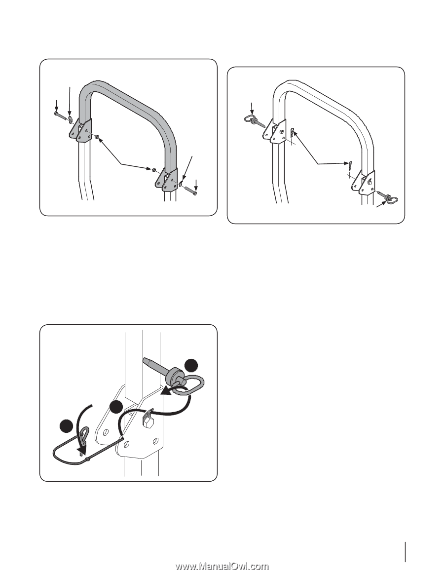
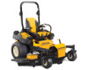
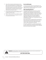
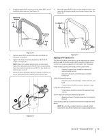
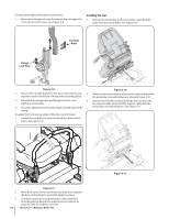
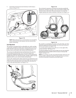
4. Install the upper ROPS section onto the lower ROPS "posts". 8. Move the upper ROPS section to the upright position, and Install the bolts and nuts. See Figure 3-5. insert the locking pins with their retainer hairpin clips. See Figure 3-7. Retaining Washer Bolt Locking Pin Lock Nuts Retaining Washer Bolt Retainer Hairpin Clips Figure 3-5 5. Tighten upper ROPS section bolts after both RH & LH hardware is installed. 6. Tighten the frame mounting hardware to 80-90 lb.-ft. torque. See Figure 3-4. NOTE: Make sure tubular upright posts are absolutely tight within welded bracket. If the ROPS is not absolutely tight after tightening hardware to 80-90 ft-lbs, additional tightening is needed. 7. Route the nylon lanyard as shown in Figure 3-6. Be sure to secure the lanyard to the retaining clip and clevis pin. B A C Locking Pin Figure 3-7 Adjusting Drive Control Levers The RH and LH drive control levers can be adjusted up or down and fore-and-aft for the comfort of the operator. Proper drive control lever and seat adjustment will result in the following: In the neutral position with hands on the control levers, • Operator's upper arms should be relaxed and approximately vertical. • Operator's forearms should be approximately horizontal. In the full forward position, • Operator's back should stay in contact with the seat back. • Control levers should not contact operator's legs. In the full reverse position, • Control levers should not contact the operator's legs or torso. Set the seat to the preferred operating position. • Adjustment lever is located under the front edge of the seat. Check factory settings of control levers for the conditions listed above. NOTE: If control lever adjustments are required, height adjustments should be made prior to angular adjustments. Figure 3-6 Section 2 - Assembly & Set-Up 13
-
 1
1 -
2
-
3
-
4
-
5
-
6
-
7
-
 8
8 -
 9
9 -
 10
10 -
 11
11 -
 12
12 -
 13
13 -
 14
14 -
 15
15 -
 16
16 -
 17
17 -
 18
18 -
19
-
20
-
21
-
22
-
23
-
24
-
25
-
26
-
27
-
28
-
29
-
30
-
31
-
32
-
33
-
34
-
35
-
36
-
37
-
38
-
39
-
40
-
41
-
42
-
43
-
44
-
45
-
46
-
47
-
48
 |
 |