Cub Cadet TANK LZ 60 TANK L 60 KW Operator's Manual - Page 35
Deck Removal
 |
View all Cub Cadet TANK LZ 60 manuals
Add to My Manuals
Save this manual to your list of manuals |
Page 35 highlights
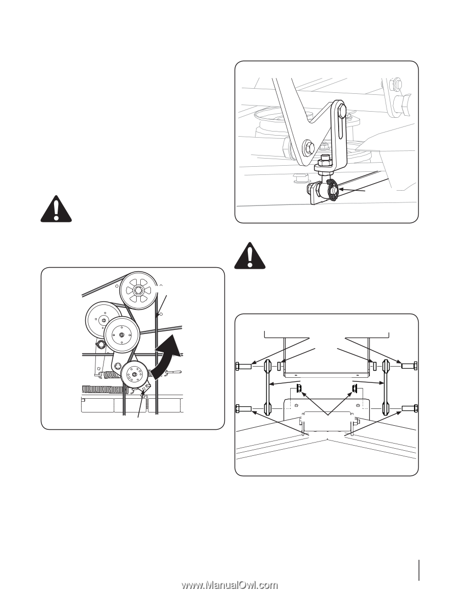
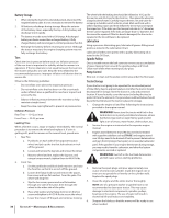
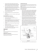
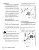
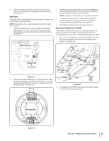
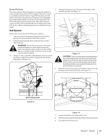
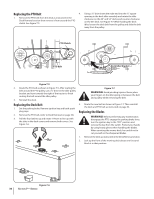
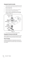
Electric PTO Clutch 5. This clutch operates when the engine is running, the operator is in the operator's seat and the PTO is engaged. This electric clutch is a normally trouble free device. If a problem develops and the blades do not turn, first check the 25 amp fuse, then investigate the wiring harness and the connections to the seat switch, the PTO switch and the electric blade clutch. Then check the seat switch, the PTO switch and finally the electric blade clutch. If the PTO clutch is still not working properly, see an authorized service dealer. Deck Removal Remove the mower deck from the tractor as follows: 1. Lower the deck to the ground. Capture the deck lift by placing the clevis pin behind the lowest position. 2. Apply the parking brake. Remove ignition key and the spark plug cap. WARNING! The muffler at the rear of the tractor may be extremely hot, and could cause serious burns. Use extreme caution when near the muffler. Allow the muffler to fully cool before removing the belt from the PTO pulley. 4. Using a 1⁄2" drive in the idler pulley bracket, turn the wrench towards the right of the tractor and slide the belt off the PTO pulley. See Figure 7-2. PTO Belt 6. Remove the four lynch pins that secure the deck to the deck lift assembly. See Figure 7-3. Lynch Pin Figure 7-3 CAUTION: There is a certain amount of spring tension due to the weight of the deck. When removing the lift linkage from the deck the tension of the springs will go from the deck to the deck lift pedal. Not capturing the deck lift pedal while removing the lift linkage from the deck will cause it to snap back. Remove the hex screw, spacer and flange lock nut securing the deck control rods to the deck. See Figure 7-4. Hex Screws Spacer Front Deck Rods Idler Pulley Bracket Figure 7-2 Flange Lock Nuts Hex Screws Figure 7-4 7. Turn front wheels as if to make a pivot turn. 8. Shift the deck toward the right side of the mower and remove. 9. To install reverse the process. Section 7 - Service 35
-
 1
1 -
2
-
3
-
4
-
5
-
6
-
7
-
8
-
9
-
10
-
11
-
12
-
13
-
14
-
15
-
16
-
17
-
18
-
19
-
20
-
21
-
22
-
23
-
24
-
25
-
26
-
27
-
28
-
29
-
 30
30 -
 31
31 -
 32
32 -
 33
33 -
 34
34 -
 35
35 -
 36
36 -
 37
37 -
 38
38 -
 39
39 -
 40
40 -
41
-
42
-
43
-
44
-
45
-
46
-
47
-
48
 |
 |