Cub Cadet TANK LZ 60 TANK L 60 KW Operator's Manual - Page 32
Deck Wheels, Parking Brake Handle
 |
View all Cub Cadet TANK LZ 60 manuals
Add to My Manuals
Save this manual to your list of manuals |
Page 32 highlights
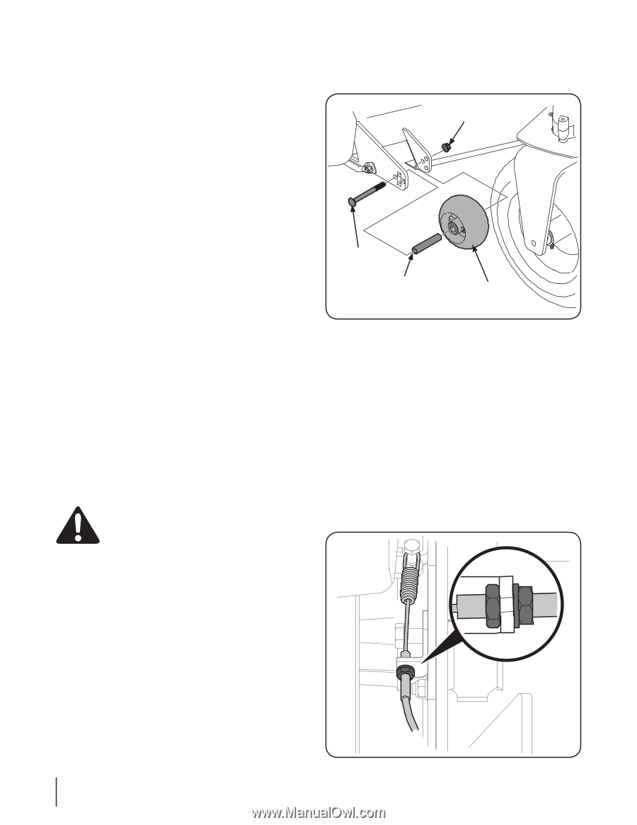
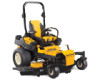
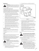
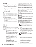
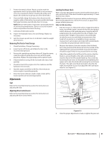
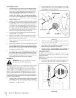
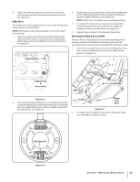
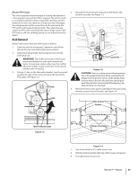
Front-to-Back Leveling 1. Park the mower on a flat paved surface, engage the parking brake, shut off the engine, remove the key from the ignition switch, disconnect the spark plug wires, using the deck lift pedal position the mowing deck into the 4" height of cut position (the 4" height of cut position is recommended in order for one to see and obtain a measurement. Any height of cut position is acceptable as long as a proper measurement can be taken) and rotate both outside blades so that they are parallel with the tractor. 2. Measure the blade-to-ground height at the right rear blade tip. Again be sure to measure at the blade tip at the rear of the right blade when aligned along the mower centerline. The blade-to-ground height at the rear of the blade tip should be 1⁄8" to 1⁄4" higher than the front tip. This is referred to as blade pitch. The same height difference should be true for the left blade, measured front and back. The pitch should not exceed 1⁄16" if cut height is below 1-1⁄2". 3. Loosen the jam nuts at the rear left and right of the deck eyebolts. Refer to Figure 6-2. 4. Start at the rear right to raise the rear of the deck, tighten the upper jam nut to raise the deck or loosen the upper jam nut to lower the rear of the deck. 5. Adjust the jam nut at the rear left to take the "slack" out of the threaded rod. 6. Tighten both lower jam nuts to secure the deck adjustment. 7. The final adjustment would be to take the "slack" out of the left rear linkage if the rear of the deck was raised by adjusting the jam nuts on the eyebolt. Loosen the jam nuts and tighten the upper nut to remove "slack". 8. In many cases it will be necessary to adjust deck height using both eyebolt adjustments and pitch adjustment to achieve the correct blade-to-ground heights. If you remember that the front right blade tip adjustment is fixed and you level to that height, adjusting the decks will be simplified. Deck Wheels WARNING! Keep hands and feet away from the discharge opening of the cutting deck. 2. Remove the flange lock nut and carriage bolt securing the front deck wheel and spacer to the deck. Remove the wheel and carriage bolt. Refer to Figure 6-3. Flange Lock Nut Carriage Bolt Spacer Deck Wheel Figure 6-3 3. Determine which index hole will give the deck wheel a 1⁄4" to 1⁄2" clearance with the ground. 4. Insert the carriage bolt through the appropriate index hole in the deck wheel bracket, through the spacer, the deck wheel and out the other side of the bracket. 5. Note the index hole of the just adjusted wheel, and adjust the other deck wheel to the same height as instructed in step 3. Parking Brake Handle The parking brake handle should engage with moderate force. The brake cable should not require adjustment, but if necessary proceed as follows: NOTE: There is a cable for each of the transmissions, be sure to adjust both cables. 1. Locate the brake cable housing nuts on the outside of the frame and to the inside of the rear tires. See Figure 6-4. NOTE: The deck wheels are an anti-scalp feature of the deck and are not designed to support the weight of the cutting deck. The mower deck cutting height can be set using the tractor's deck lift pedal. The deck heights range from 1" to 5". The deck gauge wheel position should be approximately 1⁄4 to 1⁄2" above the ground when the deck is set in the desired height setting. Using the lift pedal, set the deck in the desired height setting, then check the gauge wheel distance from the ground below. If necessary, adjust as follows: 1. Visually check the distance between the front gauge wheels and the ground. If the gauge wheels are near or touching the ground, they should be raised. If more than 1⁄2" above the ground, they should be lowered. 32 Section 6- Maintenance & Adjustments Figure 6-4
-
 1
1 -
2
-
3
-
4
-
5
-
6
-
7
-
8
-
9
-
10
-
11
-
12
-
13
-
14
-
15
-
16
-
17
-
18
-
19
-
20
-
21
-
22
-
23
-
24
-
25
-
26
-
 27
27 -
 28
28 -
 29
29 -
 30
30 -
 31
31 -
 32
32 -
 33
33 -
 34
34 -
 35
35 -
 36
36 -
 37
37 -
38
-
39
-
40
-
41
-
42
-
43
-
44
-
45
-
46
-
47
-
48
 |
 |