Cub Cadet TANK LZ 60 TANK L 60 KW Operator's Manual - Page 33
Brake Shoes, Removing/Installing the Inner Baffle
 |
View all Cub Cadet TANK LZ 60 manuals
Add to My Manuals
Save this manual to your list of manuals |
Page 33 highlights
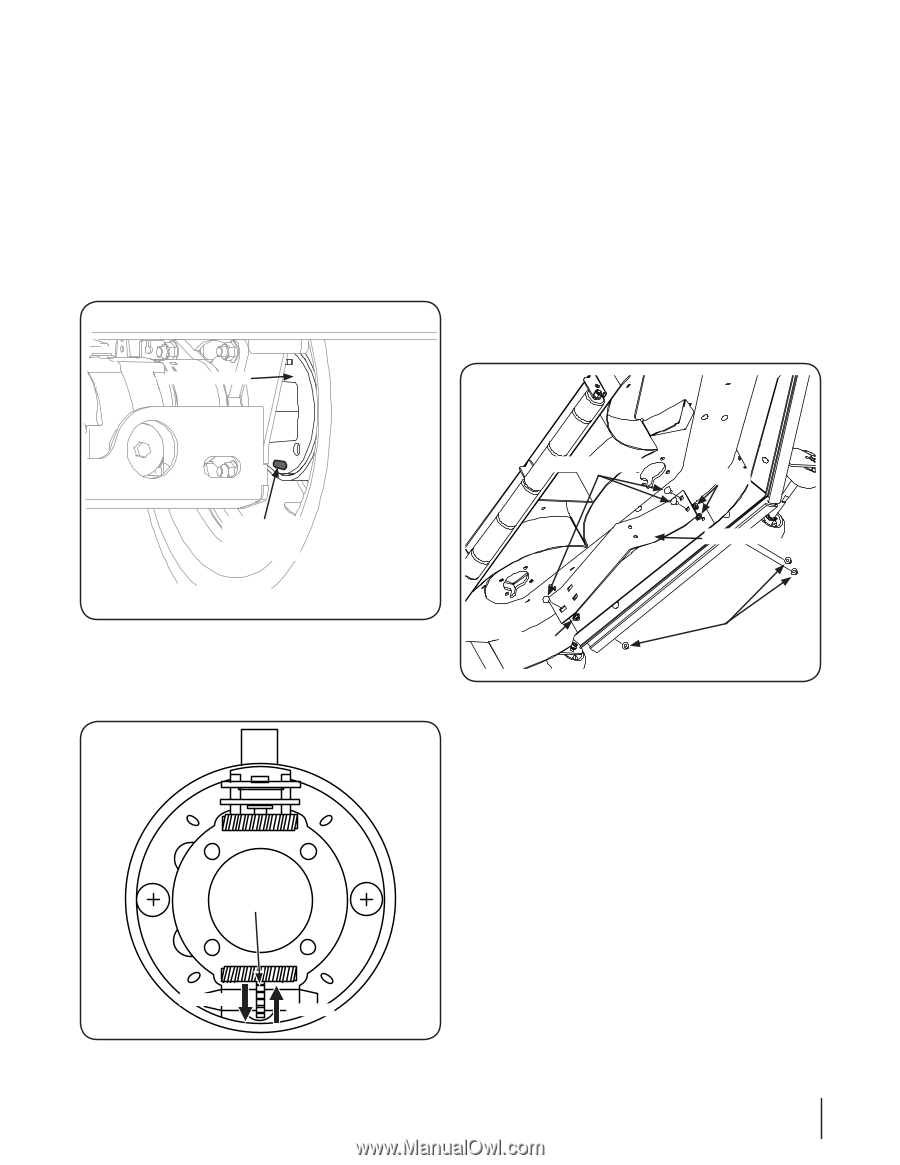
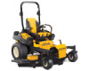
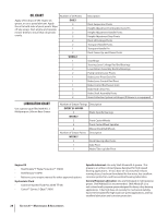
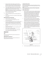
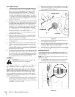
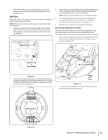
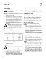
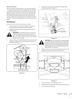
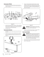
2. Adjust the cable housing nuts one full turn and check parking capacity. Repeat if parking brake does not hold. See Figure 6-4. Brake Shoes The brake shoes can be adjusted as the shoes wear. To adjust the brake shoes proceed as follows: NOTE: If the brakes need replaced, please see your Cub Cadet Service Dealer. 1. There is an access hole on the lower inside of the backing plate inside the rear tires. Locate this hole and remove the rubber plug to access the adjusting star on the brake shoes. See Figure 6-5. 3. Rotate the drum back and forth to make sure the brake shoes are not rubbing excessively, if they are rotate the adjusting star back slightly until there is just a slight rub. NOTE: A slight rub is acceptable since a used brake will seat. 4. To contract the brake shoes, rotate the star adjustment outward away from the axle until there is a slight rub between the shoes and the drum. See Figure 6-6. 5. Repeat the procedure for the opposite brake shoe. Removing/Installing the Inner Baffle The inner flow-control baffle can be removed depending on the mowing conditions. The baffle controls discharge and can be removed for high-volume grasses and installed for precision cutting. 1. Remove the carriage bolts, push nuts and flange lock nuts that secure the baffle to the deck to mow high-volume grasses. See Figure 6-7. Backing Plate Rubber Plug & Access Hole Carriage Bolts Push Nut Inner Baffle Figure 6-5 2. Using a drum brake adjusting tool, or a standard screw driver, rotate the adjusting star inward toward the axle to to expand the shoes. Expand the shoes until there is slight contact with the brake drums. See Figure 6-6. Push Nut Figure 6-7 Flange Lock Nuts 2. Re-install the inner baffle for precision cutting and make sure the baffle is properly secured. Adjusting Star Contract Expand Figure 6-6 Section 6 - Maintenance & Adjustments 33
-
 1
1 -
2
-
3
-
4
-
5
-
6
-
7
-
8
-
9
-
10
-
11
-
12
-
13
-
14
-
15
-
16
-
17
-
18
-
19
-
20
-
21
-
22
-
23
-
24
-
25
-
26
-
27
-
 28
28 -
 29
29 -
 30
30 -
 31
31 -
 32
32 -
 33
33 -
 34
34 -
 35
35 -
 36
36 -
 37
37 -
 38
38 -
39
-
40
-
41
-
42
-
43
-
44
-
45
-
46
-
47
-
48
 |
 |