Cub Cadet TANK LZ 60 TANK L 60 KW Operator's Manual - Page 34
Service
 |
View all Cub Cadet TANK LZ 60 manuals
Add to My Manuals
Save this manual to your list of manuals |
Page 34 highlights
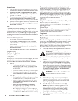
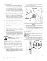
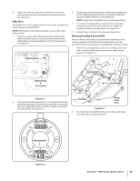
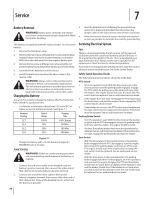
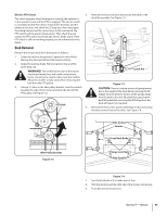
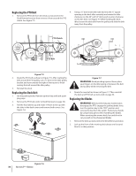
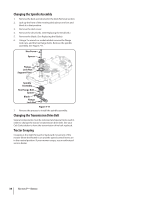
Service 7 Battery Removal WARNING! Battery posts, terminals and related accessories contain lead and lead compounds. Wash hands after handling. The battery is located beneath the seat box frame. To remove the battery: 1. Remove the hold down strap. 2. Remove the hex screw and flange lock nut securing the black negative battery lead to the negative battery post (marked NEG). Move the cable away from the negative battery post. 3. Remove the hex screw and flange lock nut securing the red positive battery lead to the positive battery post (marked POS). 4. Carefully lift the battery out of the tractor. 5. Install the battery by repeating the above steps in the reverse order. WARNING! Always connect the positive lead to the battery before connecting the negative lead. This will prevent sparking or possible injury from an electrical short caused by contacting the tractor body with tools being used to connect the cables. Charging the Battery Test and, if necessary, recharge the battery after the tractor has been stored for a period of time. • A voltmeter or load tester should read 12.6 volts (DC) or higher across the battery terminals. See Figure 7-1. Voltmeter Reading State of Charge Charging Time 12.7 100% Full Charge 12.4 75% 90 Min. 12.2 50% 180 Min. 12.0 25% 280 Min. Figure 7-1 • Charge the battery with a 12-volt battery charger at a MAXIMUM rate of 10 amps. Jump Starting WARNING!: Failure to use this starting procedure can cause sparking, and the gases in the battery to explode. 1. Connect the end of one cable to the disabled machine battery's positive terminal; then connect the other end of that cable to the booster battery's positive terminal. 2. Connect one end of the other cable to the booster battery's negative terminal; then connect the other end of that cable to the frame of the disabled tractor, as far from the battery as possible. 3. Start the disabled tractor following the normal starting instructions previously provided; then disconnect the jumper cables in the exact reverse order of their connection. 4. Have the tractor's electrical system checked and repaired as soon as possible to eliminate the need for jump starting. Servicing Electrical System Fuse There is a fuse located inside the left console. Lift the seat and look down at the left console to find the location of the fuse. A 25 amp for fuse the ignition, PTO, etc. This is a standard plug-in type automotive fuse. Always use the same capacity fuse for replacement. Check the fuse for all electrical problems. If you have a recurring problem with blown fuses, have the tractor's electrical system checked by your Cub Cadet Service Dealer. Safety Switch Operation Checks The following operational checks should be made daily: PTO Switch 1. Sit in the operator's seat. With the drive levers are in the neutral position and the parking brake engaged, engage the PTO switch by pulling up on the knob and try to start the engine. The engine should not start. If it does, the PTO switch must be replaced. See an authorized service dealer. 2. If the engine does not start, disengage the PTO by pressing the knob down and start the engine. Now enagage the PTO and the blades should rotate. 3. If the blades do not turn, the PTO switch must be replaced, the seat switch must be replaced or the electric PTO clutch must be repaired. See an authorized service dealer. Parking Brake Switch • Sit in the operator's seat. With the drive levers in the neutral position and the PTO disengaged, release the parking brake and try to start the engine. The engine should not start. • If it does, the parking brake switch must be repositioned or replaced. See an authorized service dealer. If the engine does not start, engage the parking brake and start the engine. Seat Switch • With the drive levers in the neutral position, the parking brake engaged and the PTO disengaged, start the engine. Now release the parking brake, and raise up off the seat. The engine should stop. If the engine does not stop, the seat switch must be replaced. See an authorized service dealer. • With the drive levers in the neutral position, the parking brake engaged and the PTO disengaged, sit in the operator's seat and start the engine. Enagage the PTO and the blades should start to rotate. Raise up slightly off the operator's seat and the blades should stop. If the blades do not stop when you dismount from the operator's seat, the seat switch must be replaced. See an authorized service dealer. 34
-
 1
1 -
2
-
3
-
4
-
5
-
6
-
7
-
8
-
9
-
10
-
11
-
12
-
13
-
14
-
15
-
16
-
17
-
18
-
19
-
20
-
21
-
22
-
23
-
24
-
25
-
26
-
27
-
28
-
 29
29 -
 30
30 -
 31
31 -
 32
32 -
 33
33 -
 34
34 -
 35
35 -
 36
36 -
 37
37 -
 38
38 -
 39
39 -
40
-
41
-
42
-
43
-
44
-
45
-
46
-
47
-
48
 |
 |