Cub Cadet TANK LZ 60 TANK L 60 KW Operator's Manual - Page 14
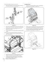
Installing the Seat
 |
View all Cub Cadet TANK LZ 60 manuals
Add to My Manuals
Save this manual to your list of manuals |
Page 14 highlights
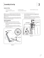
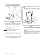
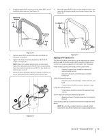
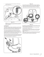
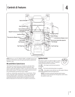
To adjust the height of the drive control levers: 1. Remove the flange lock nuts that secure the carriage bolts in the drive control levers. See Figure 3-8. Installing the Seat 1. Remove the two flange lock nuts, washers and shoulder bolts from the seat bracket. See Figure 3-10. Carriage Bolts Flange Lock Nuts Figure 3-8 2. Remove the carriage bolts from the drive control levers and 2. reposition to the second set of holes in the mounting block. 3. Reinstall the carriage bolts and flange lock nuts, and 3. tighten to 28-34 ft-lbs. 4. The same adjustments should be made to both sides of the mower. To adjust the front-to-rear angle of the drive control levers: 1. Loosen the control lever knob to unlock the drive control levers. See Figure 3-9. Figure 3-10 Place the seat into position and secure the seat into place with the previously removed hardware as shown in Figure 3-10. Remove the shoulder screw and flange lock nut from the the support cable and install the support cable with the previously removed hardware. See Figure 3-11. 2. 3. 14 Figure 3-9 Move drive control levers to the desired angle and retighten the drive control knob to secure the lapbars in place. Check the results of any adjustments to the conditions described above. Repeat any adjustment procedures as required until all conditions are met. Section 2- Assembly & Set-Up Figure 3-11
-
 1
1 -
2
-
3
-
4
-
5
-
6
-
7
-
8
-
 9
9 -
 10
10 -
 11
11 -
 12
12 -
 13
13 -
 14
14 -
 15
15 -
 16
16 -
 17
17 -
 18
18 -
 19
19 -
20
-
21
-
22
-
23
-
24
-
25
-
26
-
27
-
28
-
29
-
30
-
31
-
32
-
33
-
34
-
35
-
36
-
37
-
38
-
39
-
40
-
41
-
42
-
43
-
44
-
45
-
46
-
47
-
48
 |
 |
