Cub Cadet TANK LZ 60 TANK L 60 KW Operator's Manual - Page 15
Seat Adjustment
 |
View all Cub Cadet TANK LZ 60 manuals
Add to My Manuals
Save this manual to your list of manuals |
Page 15 highlights
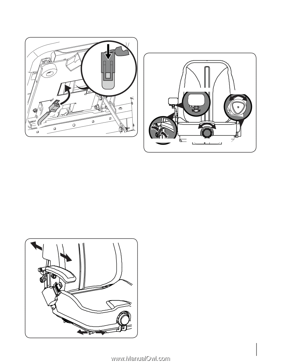
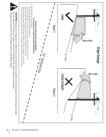
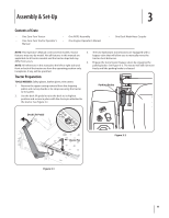
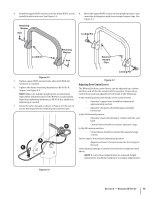
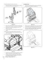
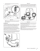
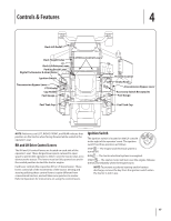
4. Insert the wiring harness into the bottom of the seat as shown in Figure 3-12. Figure 3-13 The mechanical suspension mechanism incorporates weight/ride adjustment controls for operators in the 100 to 280 lb. weight range (turn the knob on the front of the seat clockwise to increase the weight capacity and counter-clockwise to decrease. See Figure 3-14. Arm Rest Height Seat Tilt Figure 3-12 NOTE: When the harness is connected, be sure to push the excess wire from the wire harness into the seat box hole before continuing. Seat Adjustment This machine is equipped with an adjustable seat, which includes a retractable seat belt assembly and an Operator Presence Sensor (OPS). The OPS in the form of a switch, is integrated into the seat bottom and is connected to the machine electrical system. The seat can be adjusted forward and backward, the armrests can be adjusted up and down, the mechanical suspension mechanism weight/ride adjustment controls can be adjusted for weights between 125- and 275-pounds, a lumbar support can be adjusted and the seat can tilt forward and backward. To move the seat forward or back, locate the seat adjustment rod under the seat. Push the rod to the left and slide the seat forward or back into the desired position and release the rod when the seat is in the desired position. See Figure 3-13. Lumbar Support Suspension Mechanism Figure 3-14 The seat tilt is controlled by the knob on the left of the seat. Turn the knob reaward to tilt the seat back, turn the knob forward to tilt the seat forward. See Figure 3-14. To vary the lumbar support move the lever on the right of the seat up and down. See Figure 3-14. To adjust the height of the arm rests, lift the arm rest and rotate the knob under the arm rest right or left to increase or decrease the height. See Figure 3-14. NOTE: The seat base must be secured by the latch, otherwise, the seat assembly could tilt forward. The Operator Presence Sensor must be connected to the electrical wiring harness. Section 2 - Assembly & Set-Up 15
-
 1
1 -
2
-
3
-
4
-
5
-
6
-
7
-
8
-
9
-
 10
10 -
 11
11 -
 12
12 -
 13
13 -
 14
14 -
 15
15 -
 16
16 -
 17
17 -
 18
18 -
 19
19 -
 20
20 -
21
-
22
-
23
-
24
-
25
-
26
-
27
-
28
-
29
-
30
-
31
-
32
-
33
-
34
-
35
-
36
-
37
-
38
-
39
-
40
-
41
-
42
-
43
-
44
-
45
-
46
-
47
-
48
 |
 |