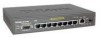
D-Link DES-3010GA Product Manual - Page 211
Viewing Optical Transceivers, D-Link DES-3010FA/GA User Guide,
 |
UPC - 790069280689
View all D-Link DES-3010GA manuals
Add to My Manuals
Save this manual to your list of manuals |
Page 211 highlights
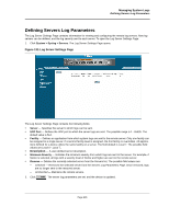
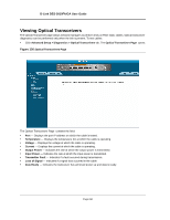
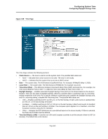
D-Link DES-3010FA/GA User Guide Viewing Optical Transceivers The Optical Transceiver page allows network managers to perform tests on Fiber Optic cables. Optical transceiver diagnostics can be performed only when the link is present. To test cables: • Click Advanced Setup > Diagnostics > Optical Transceivers tab. The Optical Transceivers Page opens: Figure 136:Optical Transceivers Page The Optical Transceivers Page contains the field: • Port - Displays the port IP address on which the cable is tested. • Temperature - Displays the temperature (C) at which the cable is operating. • Voltage - Displays the voltage at which the cable is operating. • Current - Displays the current at which the cable is operating. • Output Power - Indicates the rate at which the output power is transmitted. • Input Power - Indicates the rate at which the input power is transmitted. • Transmitter Fault - Indicates if a fault occurred during transmission. • Loss of Signal - Indicates if a signal loss occurred in the cable. • Data Ready - Indicates the transceiver has achieved power up and data is ready. Page 210
-
 1
1 -
2
-
3
-
4
-
5
-
6
-
7
-
8
-
9
-
10
-
11
-
12
-
13
-
14
-
15
-
16
-
17
-
18
-
19
-
20
-
21
-
22
-
23
-
24
-
25
-
26
-
27
-
28
-
29
-
30
-
31
-
32
-
33
-
34
-
35
-
36
-
37
-
38
-
39
-
40
-
41
-
42
-
43
-
44
-
45
-
46
-
47
-
48
-
49
-
50
-
51
-
52
-
53
-
54
-
55
-
56
-
57
-
58
-
59
-
60
-
61
-
62
-
63
-
64
-
65
-
66
-
67
-
68
-
69
-
70
-
71
-
72
-
73
-
74
-
75
-
76
-
77
-
78
-
79
-
80
-
81
-
82
-
83
-
84
-
85
-
86
-
87
-
88
-
89
-
90
-
91
-
92
-
93
-
94
-
95
-
96
-
97
-
98
-
99
-
100
-
101
-
102
-
103
-
104
-
105
-
106
-
107
-
108
-
109
-
110
-
111
-
112
-
113
-
114
-
115
-
116
-
117
-
118
-
119
-
120
-
121
-
122
-
123
-
124
-
125
-
126
-
127
-
128
-
129
-
130
-
131
-
132
-
133
-
134
-
135
-
136
-
137
-
138
-
139
-
140
-
141
-
142
-
143
-
144
-
145
-
146
-
147
-
148
-
149
-
150
-
151
-
152
-
153
-
154
-
155
-
156
-
157
-
158
-
159
-
160
-
161
-
162
-
163
-
164
-
165
-
166
-
167
-
168
-
169
-
170
-
171
-
172
-
173
-
174
-
175
-
176
-
177
-
178
-
179
-
180
-
181
-
182
-
183
-
184
-
185
-
186
-
187
-
188
-
189
-
190
-
191
-
192
-
193
-
194
-
195
-
196
-
197
-
198
-
199
-
200
-
201
-
202
-
203
-
204
-
205
-
 206
206 -
 207
207 -
 208
208 -
 209
209 -
 210
210 -
 211
211 -
 212
212 -
 213
213 -
 214
214 -
 215
215 -
 216
216 -
217
-
218
-
219
-
220
-
221
-
222
-
223
-
224
-
225
-
226
-
227
-
228
-
229
-
230
-
231
-
232
-
233
-
234
-
235
-
236
-
237
-
238
-
239
-
240
-
241
-
242
-
243
-
244
-
245
-
246
-
247
-
248
-
249
-
250
-
251
-
252
-
253
-
254
-
255
-
256
-
257
-
258
-
259
-
260
-
261
-
262
-
263
-
264
-
265
-
266
-
267
-
268
-
269
-
270
-
271
-
272
-
273
-
274
-
275
-
276
-
277
-
278
-
279
-
280
-
281
 |
 |
