D-Link DS-510S User Guide - Page 12
Hardware Installation
 |
View all D-Link DS-510S manuals
Add to My Manuals
Save this manual to your list of manuals |
Page 12 highlights
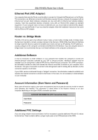
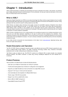
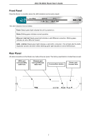
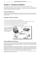
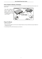
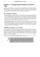
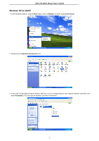
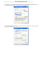
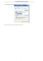
DSL-510 ADSL Router User's Guide Chapter 2 - Hardware Installation In this chapter you will learn about the various connections you will need to make in order to use the Router. When selecting the location for the Router, allow ample room to access the connections on the rear panel. For convenience, try to place the Router near your computer so you can monitor the LED indicators. Allow some space above the Router for ventilation to avoid problems with overheating. Connect the ADSL Line Use the twisted-pair ADSL cable (standard telephone cable) included with the Router to connect it to your telephone line. Simply plug one end of the cable into the ADSL port (RJ-11 receptacle) on the rear panel of the Router and insert the other end into the wall jack. Computer to Router Connection You can begin connection the Router by performing the following steps: 1. Insert one end of the ADSL cable (26 AWG twisted-pair telephone cable) into the telephone wall jack (RJ-11 port). 2. Insert the other end of the ADSL cable into the ADSL port (RJ-11 port) on the Router. 3. Insert one end of an Ethernet cable to the LAN port on the back panel of the Router. 4. Insert the other end of the Ethernet cable to the PC using Ethernet cable. You can connect the Router directly to a 10/100BASE-TX Ethernet adapter card (NIC) installed on a PC using the Ethernet cable provided as shown in this diagram. DSL-510 Connect Ethernet LAN to Router The Router may be connected to any 10/100BASE-TX Ethernet LAN. Any connection to an Ethernet concentrating device such as a switch or hub must operate at a speed of 10/100 Mbps only. When connecting the Router to any Ethernet device that is capable of operating at speeds higher than 10Mbps, be sure that the device has auto-negotiation (NWay) enabled for the connecting port. Use standard twisted-pair cable with RJ-45 connectors. The RJ-45 port on the Router is a crossed port (MDI-X). Follow standard Ethernet guidelines when deciding what type of cable to use to make this connection. When connecting the Router directly to a PC or server use a normal straight-through cable. You should use a crossed cable when connecting the Router to a normal (MDI-X) port on a switch or hub. Use a normal straight-through cable when connecting it to an uplink (MDI-II) port on a hub or switch. The Ethernet Link LED indicator will indicate a valid connection. The rules governing Ethernet cable lengths apply to the LAN to Router connection. Be sure that the cable connecting the LAN to the Router does not exceed 100 meters. 3
-
 1
1 -
2
-
3
-
4
-
5
-
6
-
 7
7 -
 8
8 -
 9
9 -
 10
10 -
 11
11 -
 12
12 -
 13
13 -
 14
14 -
 15
15 -
 16
16 -
 17
17 -
18
-
19
-
20
-
21
-
22
-
23
-
24
-
25
-
26
-
27
-
28
-
29
-
30
-
31
-
32
-
33
-
34
-
35
-
36
-
37
-
38
-
39
-
40
-
41
-
42
-
43
-
44
-
45
-
46
-
47
-
48
-
49
-
50
-
51
-
52
-
53
-
54
-
55
-
56
-
57
-
58
-
59
-
60
-
61
-
62
-
63
-
64
-
65
-
66
-
67
-
68
-
69
-
70
-
71
-
72
-
73
-
74
-
75
-
76
-
77
-
78
-
79
-
80
-
81
-
82
-
83
 |
 |
