D-Link DSN-1100-10 Hardware Reference Guide for DSN-1100-10 Valid for fir - Page 30
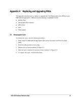
Appendix A Replacing and Upgrading FRUs
 |
UPC - 790069321559
View all D-Link DSN-1100-10 manuals
Add to My Manuals
Save this manual to your list of manuals |
Page 30 highlights
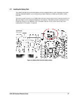
5. The connector locked firmly into connector J11 as shown in Figure A-8. Figure A-8 Battery Plug Locked in Place 6. The installed battery is shown in Figure A-9. Figure A-9 The Installed Battery 30 Appendix A Replacing and Upgrading FRUs
-
 1
1 -
2
-
3
-
4
-
5
-
6
-
7
-
8
-
9
-
10
-
11
-
12
-
13
-
14
-
15
-
16
-
17
-
18
-
19
-
20
-
21
-
22
-
23
-
24
-
 25
25 -
 26
26 -
 27
27 -
 28
28 -
 29
29 -
 30
30 -
 31
31 -
 32
32 -
 33
33 -
 34
34 -
 35
35 -
36
-
37
-
38
-
39
-
40
-
41
-
42
 |
 |

30
Appendix A Replacing and Upgrading FRUs
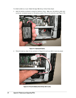
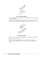
5.
The connector locked firmly into connector J11 as shown in Figure A-8.
Figure A-8
Battery Plug Locked in Place
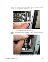
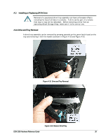
6.
The installed battery is shown in Figure A-9.
Figure A-9
The Installed Battery