D-Link DSN-1100-10 Hardware Reference Guide for DSN-1100-10 Valid for fir - Page 34
A-13. Removing a DIMM Module, A-14. Inserting a DIMM
 |
UPC - 790069321559
View all D-Link DSN-1100-10 manuals
Add to My Manuals
Save this manual to your list of manuals |
Page 34 highlights
Figure A-13. Removing a DIMM Module 7. Hold the new DIMM above the DIMM socket, so its polarization notch is located at the right end of the DIMM socket. 8. Slowly insert the new DIMM by sliding the end with the metal fingers into the DIMM socket (see Figure A-14). Stop sliding when the DIMMM is securely seated in the socket. Figure A-14. Inserting a DIMM 9. Snap the latches into place. Do not use excessive force, because the socket might break. 10. Replace the cover (see section A.1). 11. Power on the DSN-1100 storage system. If error messages relating to memory are displayed, remove the DIMM and reinstall it, making sure to seat the DIMM firmly in its socket. 34 Appendix A Replacing and Upgrading FRUs
-
 1
1 -
2
-
3
-
4
-
5
-
6
-
7
-
8
-
9
-
10
-
11
-
12
-
13
-
14
-
15
-
16
-
17
-
18
-
19
-
20
-
21
-
22
-
23
-
24
-
25
-
26
-
27
-
28
-
 29
29 -
 30
30 -
 31
31 -
 32
32 -
 33
33 -
 34
34 -
 35
35 -
 36
36 -
 37
37 -
 38
38 -
 39
39 -
40
-
41
-
42
 |
 |
34
Appendix A Replacing and Upgrading FRUs
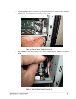
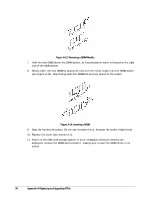
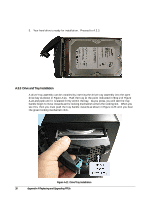
Figure A-13. Removing a DIMM Module
7.
Hold the new DIMM above the DIMM socket, so its polarization notch is located at the right
end of the DIMM socket.
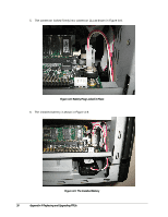
8.
Slowly insert the new DIMM by sliding the end with the metal fingers into the DIMM socket
(see Figure A-14). Stop sliding when the DIMMM is securely seated in the socket.
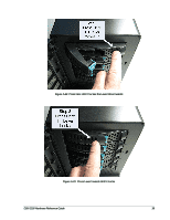
Figure A-14. Inserting a DIMM
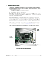
9.
Snap the latches into place. Do not use excessive force, because the socket might break.
10.
Replace the cover (see section A.1).
11.
Power on the DSN-1100 storage system. If error messages relating to memory are
displayed, remove the DIMM and reinstall it, making sure to seat the DIMM firmly in its
socket.