D-Link DSN-1100-10 Hardware Reference Guide for DSN-1100-10 Valid for fir - Page 42
A-27 Remove the Power Supply Harness Connector, A-28 Remove the Power Supply Harness
 |
UPC - 790069321559
View all D-Link DSN-1100-10 manuals
Add to My Manuals
Save this manual to your list of manuals |
Page 42 highlights
7. Remove the power supply harness connector as shown in Figure A-27. Figure A-27 Remove the Power Supply Harness Connector 8. Carefully slide the power supply out of the chassis as shown in Figure A-28. NOTE: Be sure not to damage the insulation on the wiring harness Figure A-28 Remove the Power Supply Harness Connector 9. To install a power supply, please reverse these steps. 42 Appendix A Replacing and Upgrading FRUs
-
 1
1 -
2
-
3
-
4
-
5
-
6
-
7
-
8
-
9
-
10
-
11
-
12
-
13
-
14
-
15
-
16
-
17
-
18
-
19
-
20
-
21
-
22
-
23
-
24
-
25
-
26
-
27
-
28
-
29
-
30
-
31
-
32
-
33
-
34
-
35
-
36
-
 37
37 -
 38
38 -
 39
39 -
 40
40 -
 41
41 -
 42
42
 |
 |

42
Appendix A Replacing and Upgrading FRUs
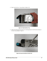
7.
Remove the power supply harness connector as shown in Figure A-27.
Figure A-27 Remove the Power Supply Harness Connector
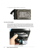
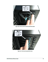
8.
Carefully slide the power supply out of the chassis as shown in Figure A-28.
NOTE: Be sure not to damage the insulation on the wiring harness
Figure A-28 Remove the Power Supply Harness Connector
9.
To install a power supply, please reverse these steps.