D-Link DSS 24 User Guide - Page 10
Side Panel, Rear Panel - port switch
 |
UPC - 790069237812
View all D-Link DSS 24 manuals
Add to My Manuals
Save this manual to your list of manuals |
Page 10 highlights
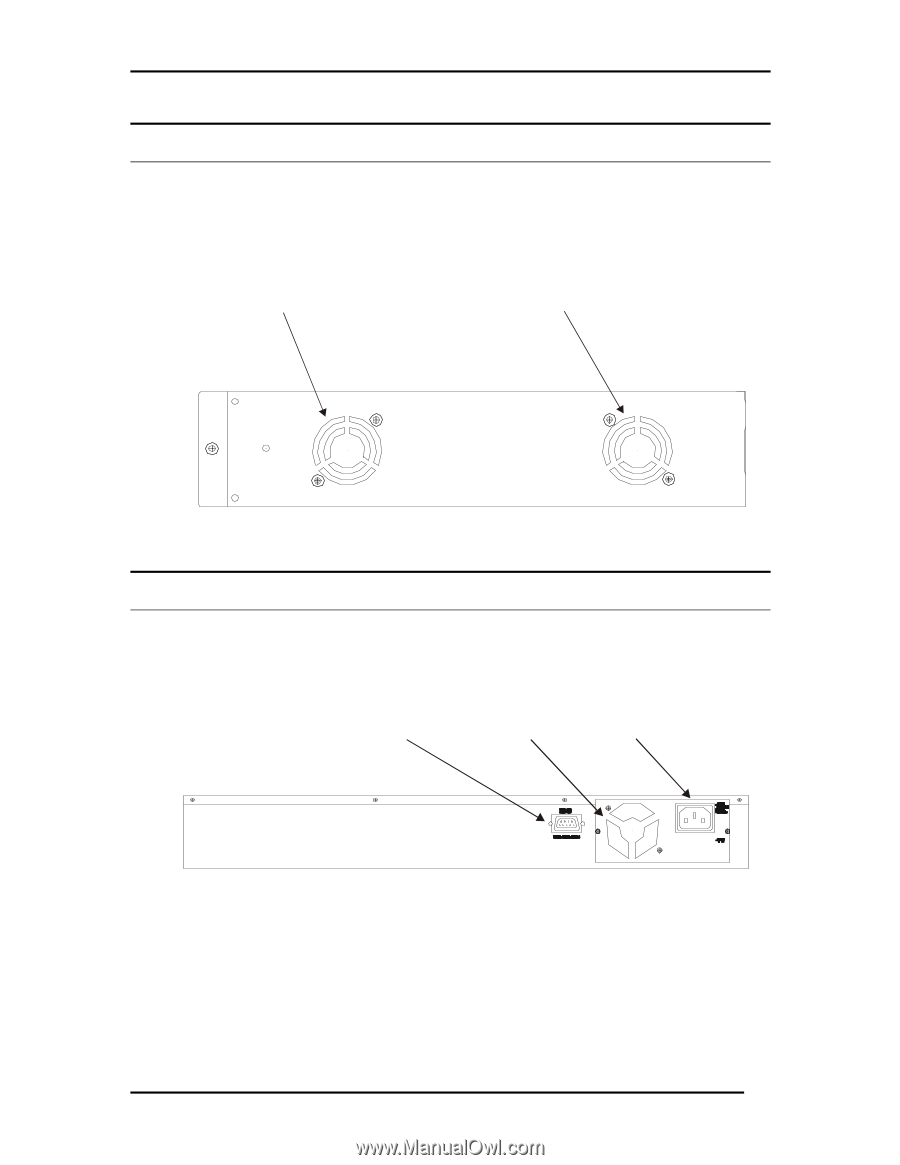
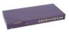
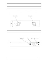
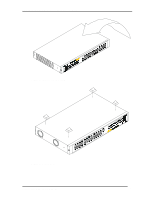
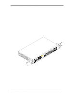
DSS-24 10/100 Auto Negotiation Switch User's Guide Side Panel There are two fans. The fans come on when the DSS-24 is powered on. The three holes on each side of the DSS-24 are used to attach the mounting brackets. There are heat vents located on the side opposite the fans. The fans and the heat vents help to cool the DSS-24. Always leave two inches of space around the DSS24 for air circulation. 40 mm Fan 40 mm Fan Figure 2: Side Panel Rear Panel The three pronged power plug, female RS-232 Console port and rear fan are located at the rear of the DSS-24, shown in Figure 3. During installation, leave enough room to allow you to plug in the power cable and attach the RS-232 cable for Local Console Management. RS-232 Port Fan Power Connector Figure 3: Rear View Introduction 4
-
 1
1 -
2
-
3
-
4
-
 5
5 -
 6
6 -
 7
7 -
 8
8 -
 9
9 -
 10
10 -
 11
11 -
 12
12 -
 13
13 -
 14
14 -
 15
15 -
16
-
17
-
18
-
19
-
20
-
21
-
22
-
23
-
24
-
25
-
26
-
27
-
28
-
29
-
30
-
31
-
32
-
33
-
34
-
35
 |
 |