Dell 810 Owners Manual - Page 140
nstall the processor in the socket. Keep the processor level see, socket. See
 |
View all Dell 810 manuals
Add to My Manuals
Save this manual to your list of manuals |
Page 140 highlights
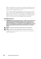
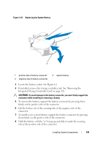
6 Align the notches in the processor with the socket keys on the ZIF socket. See Figure 3-24. 7 Install the processor in the socket. Keep the processor level (see Figure 3-24) and insert it straight down into the socket. Allow the processor to float on the pins, allowing the processor shield to hold it in place. 8 Verify that the processor is properly aligned and seated. 9 Close the processor shield. See Figure 3-24. 10 Rotate the socket-release lever down until it snaps into place. See Figure 3-24. 11 Install the heat sink. NOTE: Your kit may contain a replacement heat sink if you are installing a processor that consumes additional power. The new heat sink may not appear different than the original one; however, it has improved thermal dissipation specifications and must be used. a Using a clean lint-free cloth, remove the thermal grease from the heat sink. CAUTION: Applying too much thermal grease can result in excess grease coming in contact with and contaminating the processor socket. b Open the grease applicator included with your processor kit and apply all of the thermal grease in the applicator to the center of the topside of the new processor. c Place the heat sink on the processor. See Figure 3-23. d Close the heat-sink release levers. See Figure 3-23. 12 Replace the cooling shroud. See "Installing the Cooling Shroud" on page 97. 13 Close the system. See "Closing the System" on page 85. 14 Reconnect your system and peripherals to their electrical outlets, and turn on the system. 15 Press to enter the System Setup program, and check that the processor information matches the new system configuration. See "Entering the System Setup Program" on page 60. 140 Installing System Components
-
 1
1 -
2
-
3
-
4
-
5
-
6
-
7
-
8
-
9
-
10
-
11
-
12
-
13
-
14
-
15
-
16
-
17
-
18
-
19
-
20
-
21
-
22
-
23
-
24
-
25
-
26
-
27
-
28
-
29
-
30
-
31
-
32
-
33
-
34
-
35
-
36
-
37
-
38
-
39
-
40
-
41
-
42
-
43
-
44
-
45
-
46
-
47
-
48
-
49
-
50
-
51
-
52
-
53
-
54
-
55
-
56
-
57
-
58
-
59
-
60
-
61
-
62
-
63
-
64
-
65
-
66
-
67
-
68
-
69
-
70
-
71
-
72
-
73
-
74
-
75
-
76
-
77
-
78
-
79
-
80
-
81
-
82
-
83
-
84
-
85
-
86
-
87
-
88
-
89
-
90
-
91
-
92
-
93
-
94
-
95
-
96
-
97
-
98
-
99
-
100
-
101
-
102
-
103
-
104
-
105
-
106
-
107
-
108
-
109
-
110
-
111
-
112
-
113
-
114
-
115
-
116
-
117
-
118
-
119
-
120
-
121
-
122
-
123
-
124
-
125
-
126
-
127
-
128
-
129
-
130
-
131
-
132
-
133
-
134
-
 135
135 -
 136
136 -
 137
137 -
 138
138 -
 139
139 -
 140
140 -
 141
141 -
 142
142 -
 143
143 -
 144
144 -
 145
145 -
146
-
147
-
148
-
149
-
150
-
151
-
152
-
153
-
154
-
155
-
156
-
157
-
158
-
159
-
160
-
161
-
162
-
163
-
164
-
165
-
166
-
167
-
168
-
169
-
170
-
171
-
172
-
173
-
174
-
175
-
176
-
177
-
178
-
179
-
180
-
181
-
182
-
183
-
184
-
185
-
186
-
187
-
188
-
189
-
190
-
191
-
192
-
193
-
194
-
195
-
196
-
197
-
198
-
199
-
200
-
201
-
202
 |
 |