Dell 810 Owners Manual - Page 148
Installing the SAS Backplane, SAS B cable to the SAS B connector. See
 |
View all Dell 810 manuals
Add to My Manuals
Save this manual to your list of manuals |
Page 148 highlights
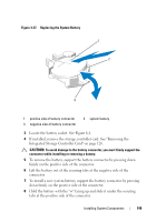
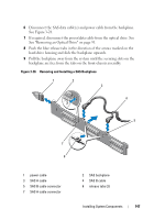
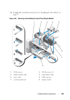
Installing the SAS Backplane 1 Align the slots on the SAS backplane with the tabs on the front-chassis assembly. 2 Slide down the SAS backplane until the blue release tabs snap into place. 3 Attach the SAS A cable to the SAS A connector on the backplane and the SAS B cable to the SAS B connector. See Figure 3-28. 4 Connect the power cable to the backplane. See Figure 3-28. 5 If applicable, connect the power/data cable to the optical drive. See "Installing an Optical Drive" on page 93. 6 Install the hard drives in their original locations. See "Installing a HardDrive Carrier" on page 89. 7 If required, route the power/data cables along the chassis wall. See step 2 and step 3 of "Sliding the Front-Chassis Assembly" on page 98. 8 Replace the cooling shroud. See "Installing the Cooling Shroud" on page 97. 9 Close the system. See "Closing the System" on page 85. 10 Reconnect the system to its electrical outlet and turn the system on, including any attached peripherals. 11 If applicable, install the front bezel. See "Installing the Front Bezel" on page 83. 148 Installing System Components
-
 1
1 -
2
-
3
-
4
-
5
-
6
-
7
-
8
-
9
-
10
-
11
-
12
-
13
-
14
-
15
-
16
-
17
-
18
-
19
-
20
-
21
-
22
-
23
-
24
-
25
-
26
-
27
-
28
-
29
-
30
-
31
-
32
-
33
-
34
-
35
-
36
-
37
-
38
-
39
-
40
-
41
-
42
-
43
-
44
-
45
-
46
-
47
-
48
-
49
-
50
-
51
-
52
-
53
-
54
-
55
-
56
-
57
-
58
-
59
-
60
-
61
-
62
-
63
-
64
-
65
-
66
-
67
-
68
-
69
-
70
-
71
-
72
-
73
-
74
-
75
-
76
-
77
-
78
-
79
-
80
-
81
-
82
-
83
-
84
-
85
-
86
-
87
-
88
-
89
-
90
-
91
-
92
-
93
-
94
-
95
-
96
-
97
-
98
-
99
-
100
-
101
-
102
-
103
-
104
-
105
-
106
-
107
-
108
-
109
-
110
-
111
-
112
-
113
-
114
-
115
-
116
-
117
-
118
-
119
-
120
-
121
-
122
-
123
-
124
-
125
-
126
-
127
-
128
-
129
-
130
-
131
-
132
-
133
-
134
-
135
-
136
-
137
-
138
-
139
-
140
-
141
-
142
-
 143
143 -
 144
144 -
 145
145 -
 146
146 -
 147
147 -
 148
148 -
 149
149 -
 150
150 -
 151
151 -
 152
152 -
 153
153 -
154
-
155
-
156
-
157
-
158
-
159
-
160
-
161
-
162
-
163
-
164
-
165
-
166
-
167
-
168
-
169
-
170
-
171
-
172
-
173
-
174
-
175
-
176
-
177
-
178
-
179
-
180
-
181
-
182
-
183
-
184
-
185
-
186
-
187
-
188
-
189
-
190
-
191
-
192
-
193
-
194
-
195
-
196
-
197
-
198
-
199
-
200
-
201
-
202
 |
 |