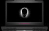
Dell Alienware 17 R4 Service Manual
Dell Alienware 17 R4 Manual
 |
View all Dell Alienware 17 R4 manuals
Add to My Manuals
Save this manual to your list of manuals |
Dell Alienware 17 R4 manual content summary:
- Dell Alienware 17 R4 | Service Manual - Page 1
Alienware 17 R4 Service Manual Regulatory Model: P31E Regulatory Type: P31E001 - Dell Alienware 17 R4 | Service Manual - Page 2
and tells you how to avoid the problem. WARNING: A WARNING indicates a potential for property damage, personal injury, or death. © 2018 - 2019 Dell Inc. or its subsidiaries. All rights reserved. Dell, EMC, and other trademarks are trademarks of Dell Inc. or its subsidiaries. Other trademarks may - Dell Alienware 17 R4 | Service Manual - Page 3
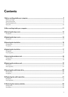
instructions...9 Recommended tools...9 Screw list...10 2 After working inside your computer 11 3 Removing the base cover...12 Procedure...12 4 Replacing Replacing the hard drive...17 Procedure...17 Post-requisites...17 7 Removing the wireless card...18 Prerequisites...18 Procedure...18 8 Replacing - Dell Alienware 17 R4 | Service Manual - Page 4
the computer base...26 Prerequisites...26 Procedure...26 16 Replacing the computer base...28 Procedure...28 Post-requisites...28 17 Removing the coin-cell battery...29 Prerequisites...29 Procedure...29 18 Replacing the coin-cell battery...30 Procedure...30 Post-requisites...30 19 Removing the - Dell Alienware 17 R4 | Service Manual - Page 5
25 Removing the system-board assembly 38 Prerequisites...38 Procedure...38 26 Replacing the system board...41 Procedure...41 Post-requisites...41 27 Removing the heat-sink assembly...42 Prerequisites...42 Procedure...42 28 Replacing the heat-sink assembly...44 Procedure...44 Post-requisites...44 29 - Dell Alienware 17 R4 | Service Manual - Page 6
51 Prerequisites...51 Procedure...51 36 Replacing the battery...52 Procedure...52 Post-requisites...52 37 Removing the touchpad...53 Prerequisites...53 Procedure...53 38 Replacing the touchpad...54 Procedure...54 Post-requisites...55 39 Removing the keyboard...56 Prerequisites...56 Procedure...56 40 - Dell Alienware 17 R4 | Service Manual - Page 7
display hinges...77 Procedure...77 Post-requisites...77 55 Removing the display back-cover and antenna assembly 78 Prerequisites...78 Procedure...78 56 Replacing the display back-cover and antenna assembly 80 Procedure...80 Post-requisites...80 57 BIOS overview...81 Entering the BIOS setup program - Dell Alienware 17 R4 | Service Manual - Page 8
Clearing BIOS (System Setup) and System passwords...84 Clearing CMOS settings...84 Flashing the BIOS...84 Boot menu...85 Boot menu enhancements...85 58 Diagnostics...86 59 Getting help and contacting Alienware 87 8 - Dell Alienware 17 R4 | Service Manual - Page 9
pins and contacts. CAUTION: You should only perform troubleshooting and repairs as authorized or directed by the Dell technical assistance team. Damage due to servicing that is not authorized by Dell is not covered by your warranty. See the safety instructions that shipped with the product or at www - Dell Alienware 17 R4 | Service Manual - Page 10
Screw type M2.5x13 Battery Computer base Palm-rest assembly Palm-rest assembly Display assembly Hard-drive assembly Hard-drive bracket Heat-sink assembly I/O board Keyboard bracket Power-adapter port M2x3 M2x2 M2.5x5 M2x3 M2.5x5 M2x3 Quantity 6 4 14 6 4 4 7 2 17 1 2 2 1 2 7 5 2 1 Screw image 10 - Dell Alienware 17 R4 | Service Manual - Page 11
that no stray screws remain inside your computer. 2. Connect any external devices, peripherals, or cables you removed before working on your computer. 3. Replace any media cards, discs, or any other parts that you removed before working on your computer. 4. Connect your computer and all attached - Dell Alienware 17 R4 | Service Manual - Page 12
computer. After working inside your computer, follow the instructions in After working inside your computer. For more safety best practices, see the Regulatory Compliance home page at www.dell.com/ regulatory_compliance. Procedure 1. Remove the six screws (M2. battery cable from the system board. 12 - Dell Alienware 17 R4 | Service Manual - Page 13
6. Press and hold the power button for five seconds to ground the system board. 13 - Dell Alienware 17 R4 | Service Manual - Page 14
best practices, see the Regulatory Compliance home page at www.dell.com/ regulatory_compliance. Procedure 1. Connect the battery cable to the system board. 2. Tighten the captive screw that secures the base cover to the computer base. 3. Replace the six screws (M2.5x13) that secure the base cover - Dell Alienware 17 R4 | Service Manual - Page 15
inside your computer, follow the instructions in After working inside your computer. the Regulatory Compliance home page at www.dell.com/ regulatory_compliance. CAUTION: Hard drives are system board. 2. Remove the hard-drive cable from the routing guides on the computer base. 3. Remove the four screws (M2 - Dell Alienware 17 R4 | Service Manual - Page 16
7. Disconnect the interposer from the hard drive. 16 - Dell Alienware 17 R4 | Service Manual - Page 17
instructions in After working inside your computer. For more safety best practices, see the Regulatory Compliance home page at www.dell.com on the hard-drive assembly with the screw holes on the computer base. 5. Replace the four screws (M2.5x5) that secure the hard-drive assembly to the computer base - Dell Alienware 17 R4 | Service Manual - Page 18
your computer. After working inside your computer, follow the instructions in After working inside your computer. For more safety best practices, see the Regulatory Compliance home page at www.dell.com/ regulatory_compliance. Prerequisites Remove the base cover. Procedure 1. Remove - Dell Alienware 17 R4 | Service Manual - Page 19
instructions in After working inside your computer. For more safety best practices, see the Regulatory Compliance home page at www.dell color scheme for the wireless card supported by your computer. Table 2. on at an angle on the wireless card before replacing it. 5. Align the screw hole on the - Dell Alienware 17 R4 | Service Manual - Page 20
your computer. After working inside your computer, follow the instructions in After working inside your computer. For more safety best practices, see the Regulatory Compliance home page at www.dell.com/ regulatory_compliance. CAUTION: Solid-state drives are fragile. Exercise care - Dell Alienware 17 R4 | Service Manual - Page 21
follow the instructions in After working inside your computer. For more safety best practices, see the Regulatory Compliance home page at www.dell.com/ screw hole on the computer base. 5. Replace the screw (M2x3) that secures the solid-state drive to the computer base. Post-requisites - Dell Alienware 17 R4 | Service Manual - Page 22
inside your computer. After working inside your computer, follow the instructions in After working inside your computer. For more safety best practices, see the Regulatory Compliance home page at www.dell.com/ regulatory_compliance. Prerequisites Remove the base cover. Procedure 1. - Dell Alienware 17 R4 | Service Manual - Page 23
your computer, follow the instructions in After working inside your computer. For more safety best practices, see the Regulatory Compliance home page at www.dell.com/ regulatory_compliance. Procedure 1. the click, remove the memory module and reinstall it. Post-requisites Replace the base cover. 23 - Dell Alienware 17 R4 | Service Manual - Page 24
your computer. After working inside your computer, follow the instructions in After working inside your computer. For more safety best practices, see the Regulatory Compliance home page at www.dell.com/ regulatory_compliance. Prerequisites Remove the base cover. Procedure 1. Remove - Dell Alienware 17 R4 | Service Manual - Page 25
instructions in After working inside your computer. For more safety best practices, see the Regulatory Compliance home page at www.dell.com/ regulatory_compliance. Procedure 1. Align the tabs on the rear-I/O cover with the slots on the computer base and snap the rear-I/O cover into place. 2. Replace - Dell Alienware 17 R4 | Service Manual - Page 26
inside your computer, follow the instructions in After working inside your computer. the Regulatory Compliance home page at www.dell.com/ regulatory_compliance. Prerequisites 1. Remove the routing and remove the antenna cables from the routing guides on the computer base. 2. Disconnect the tron-light - Dell Alienware 17 R4 | Service Manual - Page 27
6. Using a plastic scribe, gently release the tabs on the computer base from the slots on the palm-rest assembly. 7. Lift the computer base off the palm-rest assembly. 27 - Dell Alienware 17 R4 | Service Manual - Page 28
, follow the instructions in After working inside your computer. For more safety best practices, see the Regulatory Compliance home page at www.dell.com/ regulatory_compliance. Procedure 1. Align the screw holes on the computer base with the screw holes on the palm-rest assembly. 2. Replace the 14 - Dell Alienware 17 R4 | Service Manual - Page 29
. After working inside your computer, follow the instructions in After working inside your computer. For more safety best practices, see the Regulatory Compliance home page at www.dell.com/ regulatory_compliance. CAUTION: Removing the coin-cell battery resets the BIOS setup program's settings to - Dell Alienware 17 R4 | Service Manual - Page 30
the coin-cell battery cable through the routing guide and adhere the tape that secures the coin-cell battery cable to the system board. Post-requisites 1. Replace the computer base. 2. Replace the rear-I/O cover. 3. Replace the solid-state drive. 4. Replace the wireless card. 5. Replace the base - Dell Alienware 17 R4 | Service Manual - Page 31
inside your computer, follow the instructions in After working inside your computer. see the Regulatory Compliance home page at www.dell.com/ regulatory_compliance. Prerequisites 1. Remove the base Remove the speaker cable from the routing guides on the palm-rest assembly. 3. Lift the speakers along - Dell Alienware 17 R4 | Service Manual - Page 32
at www.dell.com/ regulatory_compliance. Procedure 1. Using the alignment posts, place the speakers on the palm-rest assembly. 2. Route the speaker cable through the routing guides on the palm-rest assembly. 3. Connect the speaker cable to the system board. Post-requisites 1. Replace the computer - Dell Alienware 17 R4 | Service Manual - Page 33
your computer. After working inside your computer, follow the instructions in After working inside your computer. For more safety best practices , see the Regulatory Compliance home page at www.dell.com/ regulatory_compliance. Prerequisites 1. Remove the base cover. 2. Remove the - Dell Alienware 17 R4 | Service Manual - Page 34
34 - Dell Alienware 17 R4 | Service Manual - Page 35
instructions in After working inside your computer. For more safety best practices, see the Regulatory Compliance home page at www.dell Post-requisites 1. Replace the computer base. 2. Replace the rear-I/O cover. 3. Replace the solid-state drive. 4. Replace the wireless card. 5. Replace the base - Dell Alienware 17 R4 | Service Manual - Page 36
your computer. After working inside your computer, follow the instructions in After working inside your computer. For more safety best practices , see the Regulatory Compliance home page at www.dell.com/ regulatory_compliance. Prerequisites 1. Remove the base cover. 2. Remove the - Dell Alienware 17 R4 | Service Manual - Page 37
, follow the instructions in After working inside your computer. For more safety best practices, see the Regulatory Compliance home page at www.dell.com/ regulatory_compliance. Procedure 1. Align the screw holes on the subwoofer with the screw holes on the palm-rest assembly. 2. Replace the two - Dell Alienware 17 R4 | Service Manual - Page 38
see the Regulatory Compliance home page at www.dell.com/ regulatory_compliance. NOTE: Your computer's Service Tag is stored in the system board. You must enter the Service Tag in the BIOS setup program after you replace the system board. NOTE: Replacing the system board removes any changes you have - Dell Alienware 17 R4 | Service Manual - Page 39
9. Peel off the tape that secures the coin-cell battery cable to the system board. 10. Disconnect the power- Open the latch and disconnect the I/O-board cable from the I/O board. 17. Open the latch and disconnect the keyboard cable from the system board. 18. Open the latch and disconnect the touch - Dell Alienware 17 R4 | Service Manual - Page 40
22.Remove the heat-sink assembly. 23.After performing all the above steps, you are left with the system board. 40 - Dell Alienware 17 R4 | Service Manual - Page 41
see the Regulatory Compliance home page at www.dell.com/ regulatory_compliance. NOTE: Your computer's Service Tag is stored in the system board. You must enter the Service Tag in the BIOS setup program after you replace the system board. NOTE: Replacing the system board removes any changes you have - Dell Alienware 17 R4 | Service Manual - Page 42
inside your computer, follow the instructions in After working inside your computer. For see the Regulatory Compliance home page at www.dell.com/ regulatory_compliance. NOTE: The heat sink over. 2. Disconnect the fan cable from the system board. 3. Disconnect the fan cable from the system board - Dell Alienware 17 R4 | Service Manual - Page 43
43 - Dell Alienware 17 R4 | Service Manual - Page 44
, see the Regulatory Compliance home page at www.dell.com/ regulatory_compliance. CAUTION: Incorrect alignment of the heat sink can damage the system board and processor. NOTE: If either the system board or the fan and heat-sink assembly is replaced, use the thermal pad/paste provided in the - Dell Alienware 17 R4 | Service Manual - Page 45
computer. After working inside your computer, follow the instructions in After working inside your computer. For more safety best practices, see the Regulatory Compliance home page at www.dell.com/ regulatory_compliance. Prerequisites 1. Remove the base cover. 2. guides on the palm-rest assembly. 45 - Dell Alienware 17 R4 | Service Manual - Page 46
. 5. Route the power-adapter port cable through the routing guides on the palm-rest assembly. Post-requisites 1. Replace the computer base. 2. Replace the rear-I/O cover. 3. Replace the memory modules. 4. Replace the solid-state drive. 5. Replace the wireless card. 6. Replace the base cover. 46 - Dell Alienware 17 R4 | Service Manual - Page 47
your computer. After working inside your computer, follow the instructions in After working inside your computer. For more safety best practices, see the Regulatory Compliance home page at www.dell.com/ regulatory_compliance. Prerequisites 1. Remove the base cover. 2. Remove - Dell Alienware 17 R4 | Service Manual - Page 48
working inside your computer. After working inside your computer, follow the instructions in After working inside your computer. For more safety best practices, see the Regulatory Compliance home page at www.dell.com/ regulatory_compliance. Procedure 1. Using the alignment posts, place the power - Dell Alienware 17 R4 | Service Manual - Page 49
your computer. After working inside your computer, follow the instructions in After working inside your computer. For more safety best practices, see the Regulatory Compliance home page at www.dell.com/ regulatory_compliance. Prerequisites 1. Remove the base cover. 2. Remove - Dell Alienware 17 R4 | Service Manual - Page 50
, follow the instructions in After working inside your computer. For more safety best practices, see the Regulatory Compliance home page at www.dell.com/ regulatory_compliance. Procedure 1. Align the screw holes on the display hinges with the screw holes on the palm-rest assembly. 2. Replace the six - Dell Alienware 17 R4 | Service Manual - Page 51
the instructions in After working inside your computer. For more safety best practices, see the Regulatory Compliance home page at www.dell.com/ Remove the four screws (M2.5x5) that secure the battery to the palm-rest assembly. 2. Lift the battery, along with its cable, off the palm-rest assembly. 51 - Dell Alienware 17 R4 | Service Manual - Page 52
see the Regulatory Compliance home page at www.dell.com/ regulatory_compliance. Procedure 1. Using the alignment post, place the battery on the palm-rest assembly. 2. Align the screw holes on the battery with the screw holes on the palm-rest assembly. 3. Replace the four screws (M2.5x5) that secure - Dell Alienware 17 R4 | Service Manual - Page 53
your computer, follow the instructions in After working inside your computer. the Regulatory Compliance home page at www.dell.com/ regulatory_compliance. Prerequisites 1. Remove the cover. 5. Remove the computer base. 6. Remove the battery. Procedure 1. Open the latch and disconnect the touchpad cable - Dell Alienware 17 R4 | Service Manual - Page 54
instructions in After working inside your computer. For more safety best practices, see the Regulatory Compliance home page at www.dell. on the touchpad bracket with the screw holes on the palm-rest assembly. 3. Replace the five screws (M2x3) that secure the touchpad bracket to the palm-rest assembly - Dell Alienware 17 R4 | Service Manual - Page 55
Post-requisites 1. Replace the battery. 2. Replace the computer base. 3. Replace the rear-I/O cover. 4. Replace the solid-state drive. 5. Replace the wireless card. 6. Replace the base cover. 55 - Dell Alienware 17 R4 | Service Manual - Page 56
the subwoofer. 10. Remove the power-adapter port. 11. Remove the battery. Procedure 1. Remove the 17 screws (M2x3) that secure the keyboard bracket to the palm-rest assembly. 2. Lift the keyboard bracket off the palm-rest assembly. 3. Lift the keyboard at an angle and remove it from the tabs on the - Dell Alienware 17 R4 | Service Manual - Page 57
57 - Dell Alienware 17 R4 | Service Manual - Page 58
Replacing the keyboard NOTE: Before working inside your computer, read the safety information that shipped with your computer and follow the steps in Before working inside your computer. After working inside your computer, follow the instructions in After working inside your computer. For more - Dell Alienware 17 R4 | Service Manual - Page 59
-requisites 1. Replace the battery. 2. Replace the power-adapter port. 3. Replace the subwoofer. 4. Replace the I/O board. 5. Replace the coin-cell battery. 6. Replace the computer base. 7. Replace the rear-I/O cover. 8. Replace the memory modules. 9. Replace the solid-state drive. 10. Replace the - Dell Alienware 17 R4 | Service Manual - Page 60
inside your computer, follow the instructions in After working inside your computer. the Regulatory Compliance home page at www.dell.com/ regulatory_compliance. Prerequisites 1. Remove the port. 13. Remove the battery. 14. Remove the touchpad. 15. Remove the keyboard. 16. Remove the display assembly - Dell Alienware 17 R4 | Service Manual - Page 61
home page at www.dell.com/ regulatory_compliance. Procedure Place the palm rest on a flat surface. Post-requisites 1. Replace the display assembly. 2. Replace the keyboard. 3. Replace the touchpad. 4. Replace the battery. 5. Replace the power-adapter port. 6. Replace the power-button board - Dell Alienware 17 R4 | Service Manual - Page 62
your computer. After working inside your computer, follow the instructions in After working inside your computer. For more safety best practices, see the Regulatory Compliance home page at www.dell.com/ regulatory_compliance. Prerequisites 1. Remove the base cover. 2. Remove - Dell Alienware 17 R4 | Service Manual - Page 63
5. Remove the tobii eye-tracker module. 63 - Dell Alienware 17 R4 | Service Manual - Page 64
your computer. After working inside your computer, follow the instructions in After working inside your computer. For more safety best practices, see the Regulatory Compliance home page at www.dell.com/ regulatory_compliance. Procedure 1. Replace the tobii eye-tracker module. 2. Connect the tobii - Dell Alienware 17 R4 | Service Manual - Page 65
your computer. After working inside your computer, follow the instructions in After working inside your computer. For more safety best practices, see the Regulatory Compliance home page at www.dell.com/ regulatory_compliance. Prerequisites 1. Remove the base cover. 2. Remove - Dell Alienware 17 R4 | Service Manual - Page 66
computer. After working inside your computer, follow the instructions in After working inside your computer. For more safety best practices, see the Regulatory Compliance home page at www.dell.com/ regulatory_compliance. Procedure NOTE: After replacing the Tobii eye-tracker module, launch the EyeX - Dell Alienware 17 R4 | Service Manual - Page 67
your computer. After working inside your computer, follow the instructions in After working inside your computer. For more safety best practices , see the Regulatory Compliance home page at www.dell.com/ regulatory_compliance. Prerequisites 1. Remove the base cover. 2. Remove the - Dell Alienware 17 R4 | Service Manual - Page 68
68 - Dell Alienware 17 R4 | Service Manual - Page 69
the instructions in After working inside your computer. For more safety best practices, see the Regulatory Compliance home page at www.dell.com/ on the display back-cover and antenna assembly. 6. Replace the two screws (M2x3) that secure the logo board to the display back-cover and - Dell Alienware 17 R4 | Service Manual - Page 70
your computer. After working inside your computer, follow the instructions in After working inside your computer. For more safety best practices, see the Regulatory Compliance home page at www.dell.com/ regulatory_compliance. Prerequisites 1. Remove the base cover. 2. Remove - Dell Alienware 17 R4 | Service Manual - Page 71
71 - Dell Alienware 17 R4 | Service Manual - Page 72
working inside your computer. After working inside your computer, follow the instructions in After working inside your computer. For more safety best practices, see the Regulatory Compliance home page at www.dell.com/ regulatory_compliance. Procedure 1. Align the display panel on the display back - Dell Alienware 17 R4 | Service Manual - Page 73
your computer. After working inside your computer, follow the instructions in After working inside your computer. For more safety best practices , see the Regulatory Compliance home page at www.dell.com/ regulatory_compliance. Prerequisites 1. Remove the base cover. 2. Remove the - Dell Alienware 17 R4 | Service Manual - Page 74
working inside your computer. After working inside your computer, follow the instructions in After working inside your computer. For more safety best practices, see the Regulatory Compliance home page at www.dell.com/ regulatory_compliance. Procedure 1. Connect the camera cable to the camera module - Dell Alienware 17 R4 | Service Manual - Page 75
inside your computer, follow the instructions in After working inside your computer. For see the Regulatory Compliance home page at www.dell.com/ regulatory_compliance. Prerequisites 1. Remove the base display cable from the routing guide on the display back-cover and antenna assembly. 4. Remove - Dell Alienware 17 R4 | Service Manual - Page 76
7. Peel off the tape that secures the display hinge to the display back-cover and antenna assembly. 8. Remove the 12 screws (M2.5x3) that secure the hinges to the display back-cover and antenna assembly. 9. Lift the hinges from the display back-cover and antenna assembly. 76 - Dell Alienware 17 R4 | Service Manual - Page 77
instructions in After working inside your computer. For more safety best practices, see the Regulatory Compliance home page at www.dell.com/ regulatory_compliance. Procedure 1. Align the screw holes on the display hinges with the screw holes on the display back-cover and antenna assembly. 2. Replace - Dell Alienware 17 R4 | Service Manual - Page 78
your computer, follow the instructions in After working inside your computer the Regulatory Compliance home page at www.dell.com/ regulatory_compliance. Prerequisites 1. Remove the rear-I/O cover. 5. Remove the computer base. 6. Remove the battery. 7. Remove the memory modules. 8. Remove the display assembly - Dell Alienware 17 R4 | Service Manual - Page 79
79 - Dell Alienware 17 R4 | Service Manual - Page 80
Replace the display hinges. 2. Replace the display panel. 3. Replace the logo board. 4. Replace the camera. 5. Replace the display bezel. 6. Replace the display assembly. 7. Replace the memory modules. 8. Replace the battery. 9. Replace the computer base. 10. Replace the rear-I/O cover. 11. Replace - Dell Alienware 17 R4 | Service Manual - Page 81
video adapter, keyboard, mouse, and printer. Entering the BIOS setup program 1. Turn on or restart your computer. 2. Press F2 when the Dell logo is setup options-Main menu Main System Time System Date BIOS Version Product Name Service Tag Asset Tag CPU Type CPU Speed CPU ID CPU L1 Cache CPU - Dell Alienware 17 R4 | Service Manual - Page 82
Emulation USB PowerShare USB Wake Support SATA Operation Adapter Warnings Function the computer from standby or to disable the USB wake support feature. NOTE: If USB PowerShare is enabled, a device when you use AC adapters that are not supported by your computer. Default: Enabled Allows you - Dell Alienware 17 R4 | Service Manual - Page 83
Battery Health Intel Software Guard Extensions BIOS Recovery Performance Options CPU Performance Mode Fan flow for SupportAssist System Resolution Console and for Dell OS Recovery tool. Displays if the setup status of the optional Computrace Service from Absolute Software. Enables you to enable or - Dell Alienware 17 R4 | Service Manual - Page 84
battery. 7. Replace the base cover. Flashing the BIOS You may need to flash (update) the BIOS when an update is available or when you replace the system board. Follow these steps to flash the BIOS: 1. Turn on your computer. 2. Go to www.dell.com/support. 3. Click Product support, enter the Service - Dell Alienware 17 R4 | Service Manual - Page 85
the download is complete, navigate to the folder where you saved the BIOS update file. 9. Double-click the BIOS update file icon and follow the instructions on the screen. Boot menu This computer includes a one-time boot menu. By using this feature, you can change the sequence of devices that your - Dell Alienware 17 R4 | Service Manual - Page 86
3,5 3,6 3,7 Problem description Processor failure System board: BIOS or ROM (Read-Only Memory) failure No memory or RAM (Random-Access Memory) detected Memory or RAM (Random-Access Memory) failure Invalid memory installed System-board or chipset error Display failure Coin-cell battery failure PCI - Dell Alienware 17 R4 | Service Manual - Page 87
about Alienware products and services Dell Help & Support app www.alienware.com Tips Contact Support Online help for operating system Troubleshooting information, user manuals, setup instructions, product specifications, technical help blogs, drivers, software updates, and so on VR Support Tobii
-
 1
1 -
 2
2 -
 3
3 -
 4
4 -
 5
5 -
 6
6 -
 7
7 -
8
-
9
-
10
-
11
-
12
-
13
-
14
-
15
-
16
-
17
-
18
-
19
-
20
-
21
-
22
-
23
-
24
-
25
-
26
-
27
-
28
-
29
-
30
-
31
-
32
-
33
-
34
-
35
-
36
-
37
-
38
-
39
-
40
-
41
-
42
-
43
-
44
-
45
-
46
-
47
-
48
-
49
-
50
-
51
-
52
-
53
-
54
-
55
-
56
-
57
-
58
-
59
-
60
-
61
-
62
-
63
-
64
-
65
-
66
-
67
-
68
-
69
-
70
-
71
-
72
-
73
-
74
-
75
-
76
-
77
-
78
-
79
-
80
-
81
-
82
-
83
-
84
-
85
-
86
-
87
 |
 |

Alienware 17 R4
Service Manual
Regulatory Model: P31E
Regulatory Type: P31E001