Dell Alienware 17 R5 Service Manual
Dell Alienware 17 R5 Manual
 |
View all Dell Alienware 17 R5 manuals
Add to My Manuals
Save this manual to your list of manuals |
Dell Alienware 17 R5 manual content summary:
- Dell Alienware 17 R5 | Service Manual - Page 1
Alienware 17 R5 Service Manual Computer Model: Alienware 17 R5 Regulatory Model: P31E Regulatory Type: P31E002 - Dell Alienware 17 R5 | Service Manual - Page 2
of data and tells you how to avoid the problem. WARNING: A WARNING indicates a potential for property damage, personal injury, or death. © 2018 Dell Inc. or its subsidiaries. All rights reserved. Dell, EMC, and other trademarks are trademarks of Dell Inc. or its subsidiaries. Other trademarks may be - Dell Alienware 17 R5 | Service Manual - Page 3
Contents Before working inside your computer 10 Before you begin 10 Safety instructions 10 Recommended tools 11 Screw list 12 After working inside your computer 14 Removing the base cover 15 Procedure 15 Replacing the base cover 18 Procedure 18 Removing the hard drive 21 Prerequisites 21 - Dell Alienware 17 R5 | Service Manual - Page 4
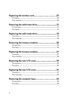
requisites 30 Removing the solid-state drive 31 Prerequisites 31 Procedure 31 Replacing the solid-state drive 33 Procedure 33 Post-requisites 34 Removing the memory modules 35 Prerequisites 35 Procedure 35 Replacing the memory modules 37 Procedure 37 Post-requisites 38 Removing the rear - Dell Alienware 17 R5 | Service Manual - Page 5
Procedure 47 Post-requisites 49 Removing the coin-cell battery 50 Prerequisites 50 Procedure 50 Replacing the coin-cell battery 52 Procedure 52 Post-requisites 53 Removing the speakers 54 Prerequisites 54 Procedure 54 Replacing the speakers 56 Procedure 56 Post-requisites 57 Removing - Dell Alienware 17 R5 | Service Manual - Page 6
Post-requisites 66 Removing the system board 67 Prerequisites 67 Procedure 67 Replacing the system board 73 Procedure 73 Post-requisites 77 Removing the heat-sink assembly 78 Prerequisites 78 Procedure 78 Replacing the heat-sink assembly 81 Procedure 81 Post-requisites 83 Removing the - Dell Alienware 17 R5 | Service Manual - Page 7
-requisites 91 Removing the display assembly 92 Prerequisites 92 Procedure 93 Replacing the display assembly 96 Procedure 96 Post-requisites 98 Removing the battery 99 Prerequisites 99 Procedure 99 Replacing the battery 101 Procedure 101 Post-requisites 102 Removing the touchpad 103 - Dell Alienware 17 R5 | Service Manual - Page 8
121 Procedure 122 Replacing the palm rest 123 Procedure 123 Post-requisites 123 Downloading drivers 125 Downloading the audio driver 125 Downloading the chipset driver 126 Downloading the graphics driver 127 Downloading the network driver 128 Downloading the tobii driver 129 Downloading - Dell Alienware 17 R5 | Service Manual - Page 9
program 135 Checking the system memory in BIOS setup program 135 System setup options 136 Troubleshooting 144 Flashing the BIOS 144 Flashing BIOS (USB key 144 Reinstall Windows using a 148 Flea power release 149 Getting help and contacting Alienware 150 Self-help resources 150 Contacting - Dell Alienware 17 R5 | Service Manual - Page 10
optical disc from your computer, if applicable. Safety instructions Use the following safety guidelines to protect your computer dell.com/ regulatory_compliance. WARNING: Disconnect all power sources before opening the computer cover or panels. After you finish working inside the computer, replace - Dell Alienware 17 R5 | Service Manual - Page 11
pins and contacts. CAUTION: You should only perform troubleshooting and repairs as authorized or directed by the Dell technical assistance team. Damage due to servicing that is not authorized by Dell is not covered by your warranty. See the safety instructions that shipped with the product or at www - Dell Alienware 17 R5 | Service Manual - Page 12
Base cover Palm-rest assembly Screw type M2.5x13 Quantity 6 Screw image Battery Palm-rest assembly Computer base Palm-rest assembly M2.5x5 4 M2. board Palm-rest assembly M2.5x5 2 Keyboard Palm-rest M2x3 17 bracket assembly Power-adapter Palm-rest M2x3 1 port bracket assembly - Dell Alienware 17 R5 | Service Manual - Page 13
Component Secured to Rear-I/O cover Computer base Screw type M2.5x7 Quantity 2 Screw image Solid-state Computer base M2x3 1 drive Subwoofer Palm-rest M2x2 2 assembly System-board Palm-rest assembly assembly M2.5x5 7 Touchpad bracket Tron-light holder Palm-rest assembly Palm-rest - Dell Alienware 17 R5 | Service Manual - Page 14
ensure that no stray screws remain inside your computer. 2 Connect any external devices, peripherals, or cables you removed before working on your computer. 3 Replace any media cards, discs, or any other parts that you removed before working on your computer. 4 Connect your computer and all attached - Dell Alienware 17 R5 | Service Manual - Page 15
your computer. After working inside your computer, follow the instructions in After working inside your computer. For more safety best practices, see the Regulatory Compliance home page at www.dell.com/regulatory_compliance. Procedure 1 Remove the six screws (M2.5x13) that - Dell Alienware 17 R5 | Service Manual - Page 16
3 Using a plastic scribe, gently pry the base cover from the gap around the captive screw to release the clips on the base cover from the computer base. 4 Lift the base cover off the computer base. 16 - Dell Alienware 17 R5 | Service Manual - Page 17
5 Disconnect the battery cable from the system board. 6 Press and hold the power button for five seconds to ground the system board. 17 - Dell Alienware 17 R5 | Service Manual - Page 18
inside your computer. After working inside your computer, follow the instructions in After working inside your computer. For more safety best practices, see the Regulatory Compliance home page at www.dell.com/regulatory_compliance. Procedure 1 Connect the battery cable to the system board. 18 - Dell Alienware 17 R5 | Service Manual - Page 19
2 Slide the base cover into the slots on the computer base. 3 Snap the base cover into place. 4 Tighten the captive screw that secures the base cover to the computer base. 19 - Dell Alienware 17 R5 | Service Manual - Page 20
5 Replace the six screws (M2.5x13) that secure the base cover to the computer base. 20 - Dell Alienware 17 R5 | Service Manual - Page 21
inside your computer, follow the instructions in After working inside your computer. For the Regulatory Compliance home page at www.dell.com/regulatory_compliance. CAUTION: Hard drives are fragile 2 Remove the hard-drive cable from the routing guides on the computer base. 3 Remove the four screws (M2 - Dell Alienware 17 R5 | Service Manual - Page 22
4 Lift the hard-drive assembly along with its cable off the computer base. 5 Remove the four screws (M3x3) that secure the hard-drive bracket to the hard-drive assembly. 6 Lift the hard-drive bracket off the hard-drive assembly. 22 - Dell Alienware 17 R5 | Service Manual - Page 23
7 Disconnect the interposer from the hard drive. 23 - Dell Alienware 17 R5 | Service Manual - Page 24
Before working inside your computer. After working inside your computer, follow the instructions in After working inside your computer. For more safety best practices, see the Regulatory Compliance home page at www.dell.com/regulatory_compliance. CAUTION: Hard drives are fragile. Exercise care when - Dell Alienware 17 R5 | Service Manual - Page 25
hard-drive bracket to the hard-drive assembly. 4 Align the screw holes on the hard-drive assembly with the screw holes on the computer base. 5 Replace the four screws (M2.5x5) that secure the hard-drive assembly to the computer base. 6 Route the hard-drive cable through the routing - Dell Alienware 17 R5 | Service Manual - Page 26
7 Connect the hard-drive cable to the system board. Post-requisites Replace the base cover. 26 - Dell Alienware 17 R5 | Service Manual - Page 27
your computer. After working inside your computer, follow the instructions in After working inside your computer. For more safety best practices, see the Regulatory Compliance home page at www.dell.com/regulatory_compliance. Prerequisites Remove the base cover. Procedure 1 Lift - Dell Alienware 17 R5 | Service Manual - Page 28
2 Remove the screw (M2x3) that secures the wireless-card bracket to the computer base. 3 Lift the wireless-card bracket off the wireless card. 4 Lift and slide the wireless card out of the wireless-card slot. 5 Disconnect the antenna cables from the wireless card. 28 - Dell Alienware 17 R5 | Service Manual - Page 29
working inside your computer. After working inside your computer, follow the instructions in After working inside your computer. For more safety best practices, see the Regulatory Compliance home page at www.dell.com/regulatory_compliance. Procedure CAUTION: To avoid damaging the wireless card, do - Dell Alienware 17 R5 | Service Manual - Page 30
4 Press the other end of the wireless card and replace the screw (M2x3) that secures the wireless-card bracket to the computer base. Post-requisites Replace the base cover. 30 - Dell Alienware 17 R5 | Service Manual - Page 31
your computer. After working inside your computer, follow the instructions in After working inside your computer. For more safety best practices, see the Regulatory Compliance home page at www.dell.com/regulatory_compliance. CAUTION: Solid-state drives are fragile. Exercise care - Dell Alienware 17 R5 | Service Manual - Page 32
3 Slide and remove the solid-state drive from the solid-state drive slot. 32 - Dell Alienware 17 R5 | Service Manual - Page 33
working inside your computer. After working inside your computer, follow the instructions in After working inside your computer. For more safety best practices, see the Regulatory Compliance home page at www.dell.com/regulatory_compliance. CAUTION: Solid-state drives are fragile. Exercise care when - Dell Alienware 17 R5 | Service Manual - Page 34
5 Replace the screw (M2x3) that secures the solid-state drive to the computer base. Post-requisites Replace the base cover. 34 - Dell Alienware 17 R5 | Service Manual - Page 35
inside your computer. After working inside your computer, follow the instructions in After working inside your computer. For more safety best practices, see the Regulatory Compliance home page at www.dell.com/regulatory_compliance. Prerequisites Remove the base cover. Procedure 1 Using - Dell Alienware 17 R5 | Service Manual - Page 36
2 Slide and remove the memory module from the memory-module slot. 36 - Dell Alienware 17 R5 | Service Manual - Page 37
Before working inside your computer. After working inside your computer, follow the instructions in After working inside your computer. For more safety best practices, see the Regulatory Compliance home page at www.dell.com/regulatory_compliance. Procedure 1 Align the notch on the memory module with - Dell Alienware 17 R5 | Service Manual - Page 38
Post-requisites Replace the base cover. 38 - Dell Alienware 17 R5 | Service Manual - Page 39
your computer. After working inside your computer, follow the instructions in After working inside your computer. For more safety best practices , see the Regulatory Compliance home page at www.dell.com/regulatory_compliance. Prerequisites Remove the base cover. Procedure 1 Remove the - Dell Alienware 17 R5 | Service Manual - Page 40
3 Pull the rear-I/O cover from the computer base. 40 - Dell Alienware 17 R5 | Service Manual - Page 41
instructions in After working inside your computer. For more safety best practices, see the Regulatory Compliance home page at www.dell.com/regulatory_compliance. Procedure 1 Align the tabs on the rear-I/O cover with the slots on the computer base and snap the rear-I/O cover into place. 2 Replace - Dell Alienware 17 R5 | Service Manual - Page 42
Post-requisites Replace the base cover. 42 - Dell Alienware 17 R5 | Service Manual - Page 43
After working inside your computer, follow the instructions in After working inside your computer. For more safety best practices, see the Regulatory Compliance home page at www.dell.com/regulatory_compliance. Prerequisites 1 Remove the base cover. 2 Follow from the routing guides on the computer base. 43 - Dell Alienware 17 R5 | Service Manual - Page 44
2 Disconnect the left and right tron-light cables from the system board. 3 Remove the two screws (M2.5x5) that secure the tron-light holder to the palm-rest assembly. 44 - Dell Alienware 17 R5 | Service Manual - Page 45
4 Remove the 14 screws (M2.5x8) that secure the computer base to the palmrest assembly. 5 Starting from left corner, pry the computer base off the palm-rest assembly. 45 - Dell Alienware 17 R5 | Service Manual - Page 46
6 Lift the computer base off the palm-rest assembly. 46 - Dell Alienware 17 R5 | Service Manual - Page 47
follow the instructions in After working inside your computer. For more safety best practices, see the Regulatory Compliance home page at www.dell.com/regulatory_compliance holes on the palm-rest assembly. 3 Replace the 14 screws (M2.5x8) that secure the computer base to the palmrest assembly. 47 - Dell Alienware 17 R5 | Service Manual - Page 48
4 Replace the two screws (M2.5x5) that secure the tron-light holder to the palm-rest assembly. 5 Connect the left and right tron-light cables to the system board. 48 - Dell Alienware 17 R5 | Service Manual - Page 49
6 Route the antenna cables through the routing guides on the computer base. Post-requisites 1 Replace the rear-I/O cover. 2 Replace the solid-state drive. 3 Replace the wireless card. 4 Follow the procedure from step 4 to step 7 in "Replacing the hard drive". 5 Replace the base cover. 49 - Dell Alienware 17 R5 | Service Manual - Page 50
. After working inside your computer, follow the instructions in After working inside your computer. For more safety best practices, see the Regulatory Compliance home page at www.dell.com/regulatory_compliance. CAUTION: Removing the coin-cell battery resets the BIOS setup program's settings to - Dell Alienware 17 R5 | Service Manual - Page 51
5 Gently peel the coin-cell battery along with its cable off the palm-rest assembly. 51 - Dell Alienware 17 R5 | Service Manual - Page 52
computer. After working inside your computer, follow the instructions in After working inside your computer. For more safety best practices, see the Regulatory Compliance home page at www.dell.com/regulatory_compliance. Procedure 1 Adhere the coin-cell battery to the palm-rest assembly. 2 Adhere the - Dell Alienware 17 R5 | Service Manual - Page 53
5 Connect the coin-cell battery cable to the system board. Post-requisites 1 Replace the computer base. 2 Replace the rear-I/O cover. 3 Replace the solid-state drive. 4 Replace the wireless card. 5 Follow the procedure from step 4 to step 7 in "Replacing the hard drive". 6 Replace the base cover. 53 - Dell Alienware 17 R5 | Service Manual - Page 54
After working inside your computer, follow the instructions in After working inside your computer. For more safety best practices, see the Regulatory Compliance home page at www.dell.com/regulatory_compliance. Prerequisites 1 Remove the base cover. 2 the routing guides on the palm-rest assembly. 54 - Dell Alienware 17 R5 | Service Manual - Page 55
3 Lift the speakers along with its cable off the palm-rest assembly. 55 - Dell Alienware 17 R5 | Service Manual - Page 56
working inside your computer. After working inside your computer, follow the instructions in After working inside your computer. For more safety best practices, see the Regulatory Compliance home page at www.dell.com/regulatory_compliance. Procedure 1 Using the alignment posts, place the speakers on - Dell Alienware 17 R5 | Service Manual - Page 57
3 Connect the speaker cable to the system board. Post-requisites 1 Replace the computer base. 2 Replace the rear-I/O cover. 3 Replace the solid-state drive. 4 Replace the wireless card. 5 Follow the procedure from step 4 to step 7 in "Replacing the hard drive". 6 Replace the base cover. 57 - Dell Alienware 17 R5 | Service Manual - Page 58
your computer. After working inside your computer, follow the instructions in After working inside your computer. For more safety best practices , see the Regulatory Compliance home page at www.dell.com/regulatory_compliance. Prerequisites 1 Remove the base cover. 2 Follow the - Dell Alienware 17 R5 | Service Manual - Page 59
4 Turn the I/O board over. 5 Disconnect the subwoofer cable. 59 - Dell Alienware 17 R5 | Service Manual - Page 60
6 Lift the I/O board off the palm-rest assembly. 60 - Dell Alienware 17 R5 | Service Manual - Page 61
working inside your computer. After working inside your computer, follow the instructions in After working inside your computer. For more safety best practices, see the Regulatory Compliance home page at www.dell.com/regulatory_compliance. Procedure 1 Connect the subwoofer cable to the I/O board - Dell Alienware 17 R5 | Service Manual - Page 62
posts, place the I/O board on the palm-rest assembly and align the screw holes on the I/O board with the screw holes on the palmrest assembly. 4 Replace the two screws (M2.5x5) that secure the I/O board to the palm-rest assembly. 5 Slide the I/O-board cable into the connector on the I/O board and - Dell Alienware 17 R5 | Service Manual - Page 63
your computer. After working inside your computer, follow the instructions in After working inside your computer. For more safety best practices , see the Regulatory Compliance home page at www.dell.com/regulatory_compliance. Prerequisites 1 Remove the base cover. 2 Follow the - Dell Alienware 17 R5 | Service Manual - Page 64
2 Lift the subwoofer along with its cable off the palm-rest assembly. 64 - Dell Alienware 17 R5 | Service Manual - Page 65
, follow the instructions in After working inside your computer. For more safety best practices, see the Regulatory Compliance home page at www.dell.com/regulatory_compliance. Procedure 1 Align the screw holes on the subwoofer with the screw holes on the palm-rest assembly. 2 Replace the two screws - Dell Alienware 17 R5 | Service Manual - Page 66
Post-requisites 1 Replace the I/O board. 2 Replace the computer base. 3 Replace the rear-I/O cover. 4 Replace the solid-state drive. 5 Replace the wireless card. 6 Follow the procedure from step 4 to step 7 in "Replacing the hard drive". 7 Replace the base cover. 66 - Dell Alienware 17 R5 | Service Manual - Page 67
, see the Regulatory Compliance home page at www.dell.com/regulatory_compliance. NOTE: Your computer's Service Tag is stored in the system board. You must enter the Service Tag in the BIOS setup program after you replace the system board. NOTE: Replacing the system board removes any changes you have - Dell Alienware 17 R5 | Service Manual - Page 68
4 Disconnect the tobii eye-tracker board cable (optional) from the system board. 5 Open the latch and disconnect the power-button board cable from the system board. 6 Disconnect the logo-board cable from the system board. 7 Turn the computer over. 8 Open the latch and disconnect the macro-keys - Dell Alienware 17 R5 | Service Manual - Page 69
Open the latch and disconnect the RGB per key keyboard cable (optional) from the system board. 16 Disconnect the speaker cable from the system board. 17 Disconnect the power-adapter port cable from the system board. 18 Disconnect the coin-cell - Dell Alienware 17 R5 | Service Manual - Page 70
19 Peel the tape that secures the coin-cell battery cable to the system board. 20 Remove the screw (M2.5x5) that secures the USB Type-C port bracket to the system board and lift the - Dell Alienware 17 R5 | Service Manual - Page 71
22 Lift the system-board assembly off the palm-rest assembly. 23 Remove the heat-sink assembly. 24 Disconnect the I/O-board cable from the back of the system board. 71 - Dell Alienware 17 R5 | Service Manual - Page 72
25 After performing all the above steps, you are left with the system board. 72 - Dell Alienware 17 R5 | Service Manual - Page 73
, see the Regulatory Compliance home page at www.dell.com/regulatory_compliance. NOTE: Your computer's Service Tag is stored in the system board. You must enter the Service Tag in the BIOS setup program after you replace the system board. NOTE: Replacing the system board removes any changes you have - Dell Alienware 17 R5 | Service Manual - Page 74
6 Replace the screw (M2.5x5) that secures the USB Type-C port bracket to the system board. 7 Slide the I/O-board cable the system board. 12 Connect the power-adapter port cable to the system board. 13 Route the coin-cell battery through the routing channel and adhere the tape to secure the cable. 74 - Dell Alienware 17 R5 | Service Manual - Page 75
-cell battery cable to the system board. 15 Slide the keyboard cable (optional) into the connector on the system board and close the latch to secure the cable. 16 Slide the keyboard-backlight cable (optional) into the connector on the system board and close the latch to secure the cable. 17 Slide - Dell Alienware 17 R5 | Service Manual - Page 76
18 Slide the macro-keys backlight cable (optional) into the connector on the system board and close the latch to secure the cable. 19 Turn the computer over. 20 Connect the logo-board cable to the system board. 21 Slide the power-button board cable into the connector on the system board and close - Dell Alienware 17 R5 | Service Manual - Page 77
cable to the system board. Post-requisites 1 Replace the memory modules. 2 Replace the computer base. 3 Replace the rear-I/O cover. 4 Replace the solid-state drive. 5 Replace the wireless card. 6 Follow the procedure from step 4 to step 7 in "Replacing the hard drive". 7 Replace the base cover. 77 - Dell Alienware 17 R5 | Service Manual - Page 78
After working inside your computer, follow the instructions in After working inside your computer. For more safety , see the Regulatory Compliance home page at www.dell.com/regulatory_compliance. WARNING: The heat sink may become the fan cable from the system board. 3 Peel off the tape that secures the - Dell Alienware 17 R5 | Service Manual - Page 79
5 Peel off the tape that secures the fan cable to the fan. NOTE: For computers shipped with NVIDIA GeForce GTX 1060 graphics controller, remove the fans after disconnecting the fan cables from the system board. 6 Turn the system-board assembly over. 7 Remove the seven screws (M2x3) that secure the - Dell Alienware 17 R5 | Service Manual - Page 80
8 Lift the heat-sink assembly off the system board. 80 - Dell Alienware 17 R5 | Service Manual - Page 81
practices, see the Regulatory Compliance home page at www.dell.com/regulatory_compliance. CAUTION: Incorrect alignment of the heat sink can damage the system board and processor. NOTE: If either the system board or the fan and heat-sink assembly is replaced, use the thermal pad provided in the kit - Dell Alienware 17 R5 | Service Manual - Page 82
2 Replace the seven screws (M2x3) that secure the heat-sink assembly to the system board. 3 Turn the system-board assembly over. NOTE: For computers shipped with NVIDIA GeForce GTX 1060 graphics controller, place the fans on the slots on the system board. 4 Connect the fan cables to their respective - Dell Alienware 17 R5 | Service Manual - Page 83
tape that secures the fan cables to the fans. Post-requisites 1 Follow the procedure from step 2 to step 18 in "Replacing the system board". 2 Replace the computer base. 3 Replace the rear-I/O cover. 4 Replace the memory modules. 5 Replace the solid-state drive. 6 Replace the wireless card. 7 Follow - Dell Alienware 17 R5 | Service Manual - Page 84
your computer. After working inside your computer, follow the instructions in After working inside your computer. For more safety best practices , see the Regulatory Compliance home page at www.dell.com/regulatory_compliance. Prerequisites 1 Remove the base cover. 2 Follow the - Dell Alienware 17 R5 | Service Manual - Page 85
5 Remove the cable from the routing guides on the palm-rest assembly. 85 - Dell Alienware 17 R5 | Service Manual - Page 86
, follow the instructions in After working inside your computer. For more safety best practices, see the Regulatory Compliance home page at www.dell.com/regulatory_compliance. power-adapter port cable through the routing guides on the palm- rest assembly, and adhere it to the palm-rest assembly. 86 - Dell Alienware 17 R5 | Service Manual - Page 87
. Post-requisites 1 Follow the procedure from step 2 to step 18 in "Replacing the system board". 2 Replace the computer base. 3 Replace the rear-I/O cover. 4 Replace the memory modules. 5 Replace the solid-state drive. 6 Replace the wireless card. 7 Follow the procedure from step 4 to step 7 in - Dell Alienware 17 R5 | Service Manual - Page 88
your computer. After working inside your computer, follow the instructions in After working inside your computer. For more safety best practices , see the Regulatory Compliance home page at www.dell.com/regulatory_compliance. Prerequisites 1 Remove the base cover. 2 Follow the - Dell Alienware 17 R5 | Service Manual - Page 89
2 Lift the power-button board along with its cable off the palm-rest assembly. 89 - Dell Alienware 17 R5 | Service Manual - Page 90
Before working inside your computer. After working inside your computer, follow the instructions in After working inside your computer. For more safety best practices, see the Regulatory Compliance home page at www.dell.com/regulatory_compliance. Procedure 1 Place the power-button board on the palm - Dell Alienware 17 R5 | Service Manual - Page 91
Post-requisites 1 Follow the procedure from step 2 to step 18 in "Replacing the system board". 2 Replace the computer base. 3 Replace the rear-I/O cover. 4 Replace the memory modules. 5 Replace the solid-state drive. 6 Replace the wireless card. 7 Follow the procedure from step 4 to step 7 in " - Dell Alienware 17 R5 | Service Manual - Page 92
your computer. After working inside your computer, follow the instructions in After working inside your computer. For more safety best practices , see the Regulatory Compliance home page at www.dell.com/regulatory_compliance. Prerequisites 1 Remove the base cover. 2 Follow the - Dell Alienware 17 R5 | Service Manual - Page 93
Procedure 1 Remove the six screws (M2.5x5) that secure the display assembly to the palmrest assembly. 2 Turn the computer over. 3 Peel the tape to remove the antenna cables from the palm-rest assembly. 4 Remove the logo board cable from the routing guides on the palm-rest assembly. 93 - Dell Alienware 17 R5 | Service Manual - Page 94
5 Remove the tobii eye-tracker cable and the display cable from the routing guides on the palm-rest assembly. 6 Push the antenna cables, logo board cable, tobii eye-tracker cable, and the display cable through the holes on the palm-rest assembly. 94 - Dell Alienware 17 R5 | Service Manual - Page 95
7 Lift the display assembly off the computer base. 95 - Dell Alienware 17 R5 | Service Manual - Page 96
working inside your computer. After working inside your computer, follow the instructions in After working inside your computer. For more safety best practices, see the Regulatory Compliance home page at www.dell.com/regulatory_compliance. Procedure 1 Place the palm-rest assembly on the display - Dell Alienware 17 R5 | Service Manual - Page 97
4 Route the antenna cables and the logo-board cable through the routing guides on the palm-rest assembly. 5 Turn the computer over. 97 - Dell Alienware 17 R5 | Service Manual - Page 98
power-adapter port. 2 Follow the procedure from step 2 to step 18 in "Replacing the system board". 3 Replace the computer base. 4 Replace the rear-I/O cover. 5 Replace the memory modules. 6 Replace the solid-state drive. 7 Replace the wireless card. 8 Follow the procedure from step 4 to step 7 in - Dell Alienware 17 R5 | Service Manual - Page 99
computer, follow the instructions in After working inside your computer. For more safety best practices, see the Regulatory Compliance home page at www.dell.com/regulatory_compliance. computer base. Procedure 1 Remove the four screws (M2.5x5) that secure the battery to the palm-rest assembly. 99 - Dell Alienware 17 R5 | Service Manual - Page 100
2 Lift the battery off the palm-rest assembly. 100 - Dell Alienware 17 R5 | Service Manual - Page 101
safety best practices, see the Regulatory Compliance home page at www.dell.com/regulatory_compliance. Procedure 1 Place the battery on the palm-rest assembly, and align the screw holes on the battery with the screw holes on the palm-rest assembly. 2 Replace the four screws (M2.5x5) that secure the - Dell Alienware 17 R5 | Service Manual - Page 102
Post-requisites 1 Replace the computer base. 2 Replace the rear-I/O cover. 3 Replace the solid-state drive. 4 Replace the wireless card. 5 Follow the procedure from step 4 to step 7 in "Replacing the hard drive". 6 Replace the base cover. 102 - Dell Alienware 17 R5 | Service Manual - Page 103
your computer, follow the instructions in After working inside your computer. the Regulatory Compliance home page at www.dell.com/regulatory_compliance. Prerequisites 1 Remove the base cover. 6 Remove the computer base. 7 Remove the battery. Procedure 1 Open the latch, and disconnect the touchpad cable - Dell Alienware 17 R5 | Service Manual - Page 104
4 Lift the touchpad bracket off the palm-rest assembly. 5 Open the computer 90 degrees, and using a plastic scribe to release the touchpad from the adhesive on the palm-rest assembly. 104 - Dell Alienware 17 R5 | Service Manual - Page 105
6 Peel the touchpad off the palm-rest assembly. CAUTION: To avoid potential damage to the alignment posts on palm-rest assembly, carefully peel the touchpad off the palm-rest assembly. 105 - Dell Alienware 17 R5 | Service Manual - Page 106
working inside your computer. After working inside your computer, follow the instructions in After working inside your computer. For more safety best practices, see the Regulatory Compliance home page at www.dell.com/regulatory_compliance. Procedure 1 Using the alignment posts on the palm-rest - Dell Alienware 17 R5 | Service Manual - Page 107
cable into the connector on the system board and close the latch to secure the cable. Post-requisites 1 Replace the battery. 2 Replace the computer base. 3 Replace the rear-I/O cover. 4 Replace the solid-state drive. 5 Replace the wireless card. 6 Follow the procedure from step 4 to step 7 in - Dell Alienware 17 R5 | Service Manual - Page 108
7 Replace the base cover. 108 - Dell Alienware 17 R5 | Service Manual - Page 109
your computer, follow the instructions in After working inside your computer. the Regulatory Compliance home page at www.dell.com/regulatory_compliance. Prerequisites 1 Remove the base cover. 7 Remove the computer base. 8 Remove the coin-cell battery. 9 Remove the I/O board. 10 Remove the subwoofer. 11 - Dell Alienware 17 R5 | Service Manual - Page 110
2 Lift the keyboard bracket off the palm-rest assembly. 3 Open the latches and disconnect the macro-keys cable and macro-keys backlight cable from the keyboard. 110 - Dell Alienware 17 R5 | Service Manual - Page 111
4 Peel off the macro-keys cable and macro-keys backlight cable from the keyboard. 111 - Dell Alienware 17 R5 | Service Manual - Page 112
5 Lift the keyboard at an angle, and remove it from the tabs on the palm-rest assembly. 112 - Dell Alienware 17 R5 | Service Manual - Page 113
working inside your computer. After working inside your computer, follow the instructions in After working inside your computer. For more safety best practices, see the Regulatory Compliance home page at www.dell.com/regulatory_compliance. Procedure CAUTION: Ensure that there are no cables under - Dell Alienware 17 R5 | Service Manual - Page 114
3 Adhere the macro-keys cable and the macro-keys backlight cable to the keyboard. 4 Align the screw holes on the keyboard bracket with the screw holes on the palm-rest assembly. 114 - Dell Alienware 17 R5 | Service Manual - Page 115
Replace the 17 screws (M2x3) that secure the keyboard bracket to the palmrest assembly. Post-requisites 1 Replace the battery. 2 Replace the power-adapter port. 3 Follow the procedure from step 2 to step 18 in "Replacing the system board". 4 Replace the subwoofer. 5 Replace the I/O board. 6 Replace - Dell Alienware 17 R5 | Service Manual - Page 116
13 Replace the base cover. 116 - Dell Alienware 17 R5 | Service Manual - Page 117
your computer, follow the instructions in After working inside your computer. the Regulatory Compliance home page at www.dell.com/regulatory_compliance. Prerequisites 1 Remove the base cover. 7 Remove the computer base. 8 Remove the coin-cell battery. 9 Remove the I/O board. 10 Remove the subwoofer. 11 - Dell Alienware 17 R5 | Service Manual - Page 118
Procedure Lift the macro keys at an angle, and release it from the tabs on the palm-rest assembly. 118 - Dell Alienware 17 R5 | Service Manual - Page 119
working inside your computer. After working inside your computer, follow the instructions in After working inside your computer. For more safety best practices, see the Regulatory Compliance home page at www.dell.com/regulatory_compliance. Procedure CAUTION: Ensure that there are no cables under - Dell Alienware 17 R5 | Service Manual - Page 120
step 2 to step 18 in "Replacing the system board". 5 Replace the subwoofer. 6 Replace the I/O board. 7 Replace the coin-cell battery. 8 Replace the computer base. 9 Replace the rear-I/O cover. 10 Replace the memory modules. 11 Replace the solid-state drive. 12 Replace the wireless card. 13 Follow - Dell Alienware 17 R5 | Service Manual - Page 121
inside your computer, follow the instructions in After working inside your computer. For see the Regulatory Compliance home page at www.dell.com/regulatory_compliance. Prerequisites 1 Remove the base cover the battery. 16 Remove the touchpad. 17 Remove the keyboard. 18 Remove the macro keys. - Dell Alienware 17 R5 | Service Manual - Page 122
Procedure After performing all the prerequisites, we are left with the palm rest. 122 - Dell Alienware 17 R5 | Service Manual - Page 123
step 18 in "Replacing the system board". 9 Replace the memory modules. 10 Replace the subwoofer. 11 Replace the I/O board. 12 Replace the speakers. 13 Replace the coin-cell battery. 14 Replace the computer base. 15 Replace the rear-I/O cover. 16 Replace the solid-state drive. 17 Replace the wireless - Dell Alienware 17 R5 | Service Manual - Page 124
19 Replace the base cover. 124 - Dell Alienware 17 R5 | Service Manual - Page 125
. 2 Go to www.dell.com/support. 3 Enter the Service Tag of your computer, and then click Submit. NOTE: If you do not have the Service Tag, use the autodetect feature or manually browse for your computer model. 4 Click Drivers & downloads. 5 Click the Detect Drivers button. 6 Review and agree to the - Dell Alienware 17 R5 | Service Manual - Page 126
. 2 Go to www.dell.com/support. 3 Enter the Service Tag of your computer, and then click Submit. NOTE: If you do not have the Service Tag, use the autodetect feature or manually browse for your computer model. 4 Click Drivers & downloads. 5 Click the Detect Drivers button. 6 Review and agree to the - Dell Alienware 17 R5 | Service Manual - Page 127
follow the instructions on the screen to install the driver. Downloading the graphics driver 1 Turn on your computer. 2 Go to www.dell.com/support. 3 Enter the Service Tag of your computer, and then click Submit. NOTE: If you do not have the Service Tag, use the autodetect feature or manually browse - Dell Alienware 17 R5 | Service Manual - Page 128
. 2 Go to www.dell.com/support. 3 Enter the Service Tag of your computer, and then click Submit. NOTE: If you do not have the Service Tag, use the autodetect feature or manually browse for your computer model. 4 Click Drivers & downloads. 5 Click the Detect Drivers button. 6 Review and agree to the - Dell Alienware 17 R5 | Service Manual - Page 129
follow the instructions on the screen to install the driver. Downloading the tobii driver 1 Turn on your computer. 2 Go to www.dell.com/support. 3 Enter the Service Tag of your computer, and then click Submit. NOTE: If you do not have the Service Tag, use the autodetect feature or manually browse - Dell Alienware 17 R5 | Service Manual - Page 130
follow the instructions on the screen to install the driver. Downloading the USB driver 1 Turn on your computer. 2 Go to www.dell.com/support. 3 Enter the Service Tag of your computer, and then click Submit. NOTE: If you do not have the Service Tag, use the autodetect feature or manually browse for - Dell Alienware 17 R5 | Service Manual - Page 131
. 2 Go to www.dell.com/support. 3 Enter the Service Tag of your computer, and then click Submit. NOTE: If you do not have the Service Tag, use the autodetect feature or manually browse for your computer model. 4 Click Drivers & downloads. 5 Click the Detect Drivers button. 6 Review and agree to the - Dell Alienware 17 R5 | Service Manual - Page 132
14 After the download is complete, navigate to the folder where you saved the wireless driver file. 15 Double-click the wireless driver file icon and follow the instructions on the screen to install the driver. Table 6. Network adapters in Device Manager Before installation After installation 132 - Dell Alienware 17 R5 | Service Manual - Page 133
boot device order and boot directly to a specific device (for example: optical drive or hard drive). During the Power-on Self Test (POST), when the Dell logo appears, you can: • Access System Setup by pressing F2 key • Bring up the one-time boot menu by pressing F12 key The one-time - Dell Alienware 17 R5 | Service Manual - Page 134
. Use the BIOS Setup program for the following purposes: • Get information about the hardware installed in your computer, such as the amount of RAM and the size of the hard drive. • Change the system configuration information. • Set or change a user-selectable option, such as the user password - Dell Alienware 17 R5 | Service Manual - Page 135
setup program 1 Turn on or restart your computer. 2 Press F2 when the Dell logo is displayed on the screen to enter the BIOS setup program. The BIOS setup program 1 Turn on or restart your computer. 2 Press F2 when the Dell logo is displayed on the screen to enter the BIOS setup program. A list - Dell Alienware 17 R5 | Service Manual - Page 136
date in mm/dd/ yyyy format. BIOS Version Displays the BIOS version. Product Name Displays the model number of your computer. Service Tag Displays the service tag of your computer. Asset Tag Displays the asset tag of your computer. CPU Type Displays the processor type. CPU Speed Displays - Dell Alienware 17 R5 | Service Manual - Page 137
Main Second HDD Third HDD M.2 PCIe SSD-1 M.2 PCIe SSD-2 M.2 PCIe SSD-3 AC Adapter Type Displays the type of secondary harddrive installed. Displays the type of third hard-drive installed. Displays the type of primary SSD installed. Displays the type of secondary SSD installed. Displays the type of - Dell Alienware 17 R5 | Service Manual - Page 138
PowerShare is enabled, a device connected to the USB PowerShare connector may not wake the computer. Enable/disable Intel Speed Shift Technology support. Setting this option to enable to allows the operating system to select the appropriate processor performance automatically. Default: Enabled 138 - Dell Alienware 17 R5 | Service Manual - Page 139
should display warning messages when you use AC adapters that are not supported by your computer. Default: Enabled Enables you to set function key behavior. Default: Function key Enables you to charge your computer battery using Standard Charge or Express Charge mode. Default: Express Charge - Dell Alienware 17 R5 | Service Manual - Page 140
to select the CPU performance mode. Default: Enabled Fan Performance Mode Enables you to select the fan performance mode. Default: Balanced Mode Core Over automatic boot flow for SupportAssist System Resolution Console and for Dell OS Recovery tool. Default: 2 SupportAssist OS Recovery Enable - Dell Alienware 17 R5 | Service Manual - Page 141
password or HDD password changes. Default: Permitted Computrace Firmware TPM Enable or disable the BIOS module interface of the optional Computrace Service from Absolute Software. Default: Activate Enables you to enable or disable the firmware TPM function. Default: Enabled PPI Bypass for Clear - Dell Alienware 17 R5 | Service Manual - Page 142
Security UEFI Capsule Firmware Updates When enabled, this setting will allow the OS to skip BIOS PPI user prompts when issuing the Clear command. Changes to this setting take effect immediately. Default: Enabled Enable or disable BIOS updates through UEFI capsule update packages. Default: Enabled - Dell Alienware 17 R5 | Service Manual - Page 143
Boot Boot Option #3 Displays the available third boot option. Table 11. System setup options-Exit menu Exit Save Changes and Reset Allows you to exit system setup and save your changes. Discard Changes and Reset Allows you to exit system setup and load previous values for all system setup - Dell Alienware 17 R5 | Service Manual - Page 144
Troubleshooting Flashing the BIOS You may need to flash (update) the BIOS when an update is available or when you replace the system board. Follow these steps to flash the BIOS: 1 Turn on your computer. 2 Go to www.dell.com/support. 3 Click Product support, enter the Service Tag of your computer, - Dell Alienware 17 R5 | Service Manual - Page 145
The BIOS Update Utility appears. Follow the instructions on the screen to complete the BIOS update Restart your computer. 3 Press F12 after the Dell logo is displayed on the screen to access the layout. 6 In the Choose an option screen, click Troubleshoot. 7 Click Recover from a drive. 8 Choose one - Dell Alienware 17 R5 | Service Manual - Page 146
completed successfully • View error messages that inform you of problems encountered during testing NOTE: Some tests for specific devices require terminal when the diagnostic tests are performed. For more information, see Dell EPSA Diagnostic 3.0. Running the ePSA diagnostics 1 Power-on the computer. - Dell Alienware 17 R5 | Service Manual - Page 147
12. Diagnostics Light Pattern Problem description 2,1 CPU failure 2,2 System board: BIOS and ROM failure 2,3 No memory or RAM detected 2,4 Memory or RAM failure 2,5 Invalid memory installed 2,6 System board or chipset error 2,7 LCD failure 3,1 CMOS battery failure 3,2 PCI/video - Dell Alienware 17 R5 | Service Manual - Page 148
Light Pattern 3,3 3,4 Problem description Recovery image not found Recovery image found but procedure may be performed. The following procedure provides the instructions on how to conduct a Wi-Fi power cycle: NOTE: Some ISPs (Internet Service Providers) provide a modem/router combo device. 1 Turn - Dell Alienware 17 R5 | Service Manual - Page 149
power is the residual static electricity that remains on the computer even after it has been powered off and the battery has been removed. The following procedure provides the instructions on how to conduct flea power release: 1 Turn off your computer. 2 Remove the base cover. 3 Press and hold the - Dell Alienware 17 R5 | Service Manual - Page 150
about Alienware products www.alienware.com and services Dell Help & Support app Tips Contact Support Online help for operating system Troubleshooting information, user manuals, setup instructions, product specifications, technical help blogs, drivers, software updates, and so on VR Support Tobii - Dell Alienware 17 R5 | Service Manual - Page 151
Contacting Alienware To contact Alienware for sales, technical support, or customer service issues, see www.alienware.com. NOTE: Availability varies by country and product, and some services may not be available in your country. NOTE: If you do not have an active internet connection, you can find
-
 1
1 -
 2
2 -
 3
3 -
 4
4 -
 5
5 -
 6
6 -
 7
7 -
8
-
9
-
10
-
11
-
12
-
13
-
14
-
15
-
16
-
17
-
18
-
19
-
20
-
21
-
22
-
23
-
24
-
25
-
26
-
27
-
28
-
29
-
30
-
31
-
32
-
33
-
34
-
35
-
36
-
37
-
38
-
39
-
40
-
41
-
42
-
43
-
44
-
45
-
46
-
47
-
48
-
49
-
50
-
51
-
52
-
53
-
54
-
55
-
56
-
57
-
58
-
59
-
60
-
61
-
62
-
63
-
64
-
65
-
66
-
67
-
68
-
69
-
70
-
71
-
72
-
73
-
74
-
75
-
76
-
77
-
78
-
79
-
80
-
81
-
82
-
83
-
84
-
85
-
86
-
87
-
88
-
89
-
90
-
91
-
92
-
93
-
94
-
95
-
96
-
97
-
98
-
99
-
100
-
101
-
102
-
103
-
104
-
105
-
106
-
107
-
108
-
109
-
110
-
111
-
112
-
113
-
114
-
115
-
116
-
117
-
118
-
119
-
120
-
121
-
122
-
123
-
124
-
125
-
126
-
127
-
128
-
129
-
130
-
131
-
132
-
133
-
134
-
135
-
136
-
137
-
138
-
139
-
140
-
141
-
142
-
143
-
144
-
145
-
146
-
147
-
148
-
149
-
150
-
151
 |
 |

Alienware 17 R5
Service Manual
Computer Model: Alienware 17 R5
Regulatory Model: P31E
Regulatory Type: P31E002