Dell Alienware 17 R5 Service Manual - Page 74
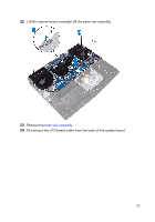
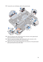
Connect the speaker cable to the system board., press down the latch to secure the cable.
 |
View all Dell Alienware 17 R5 manuals
Add to My Manuals
Save this manual to your list of manuals |
Page 74 highlights
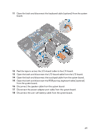
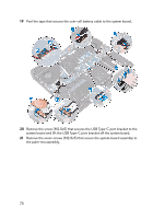
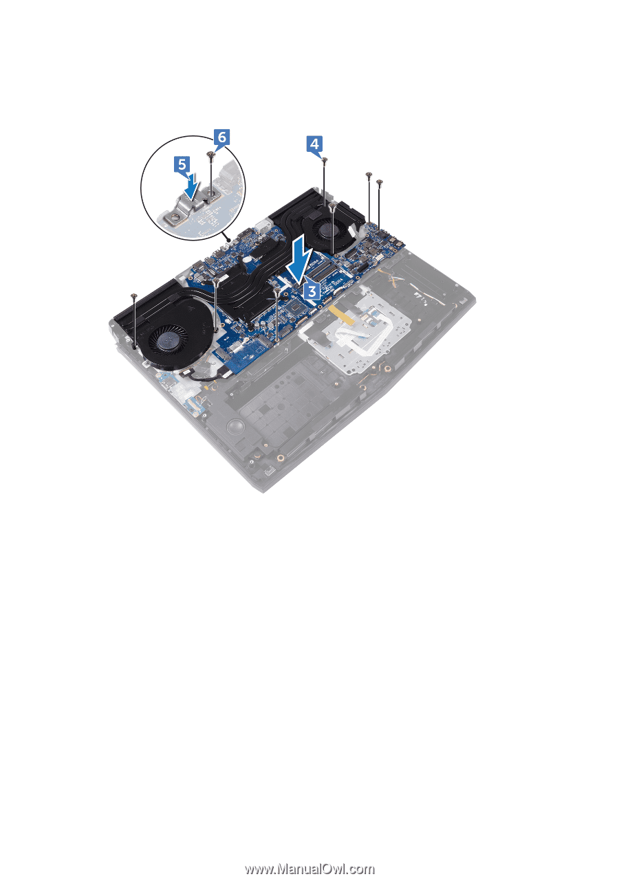
6 Replace the screw (M2.5x5) that secures the USB Type-C port bracket to the system board. 7 Slide the I/O-board cable into the connector on the I/O-board and close the latch to secure the cable. 8 Adhere the tape that secures the I/O-board cable to the I/O board. 9 Slide the touchpad cable into the connector on the system board and close the latch to secure the cable. 10 Insert the RGB per key keyboard cable (optional) into the connector and press down the latch to secure the cable. 11 Connect the speaker cable to the system board. 12 Connect the power-adapter port cable to the system board. 13 Route the coin-cell battery through the routing channel and adhere the tape to secure the cable. 74
-
 1
1 -
2
-
3
-
4
-
5
-
6
-
7
-
8
-
9
-
10
-
11
-
12
-
13
-
14
-
15
-
16
-
17
-
18
-
19
-
20
-
21
-
22
-
23
-
24
-
25
-
26
-
27
-
28
-
29
-
30
-
31
-
32
-
33
-
34
-
35
-
36
-
37
-
38
-
39
-
40
-
41
-
42
-
43
-
44
-
45
-
46
-
47
-
48
-
49
-
50
-
51
-
52
-
53
-
54
-
55
-
56
-
57
-
58
-
59
-
60
-
61
-
62
-
63
-
64
-
65
-
66
-
67
-
68
-
 69
69 -
 70
70 -
 71
71 -
 72
72 -
 73
73 -
 74
74 -
 75
75 -
 76
76 -
 77
77 -
 78
78 -
 79
79 -
80
-
81
-
82
-
83
-
84
-
85
-
86
-
87
-
88
-
89
-
90
-
91
-
92
-
93
-
94
-
95
-
96
-
97
-
98
-
99
-
100
-
101
-
102
-
103
-
104
-
105
-
106
-
107
-
108
-
109
-
110
-
111
-
112
-
113
-
114
-
115
-
116
-
117
-
118
-
119
-
120
-
121
-
122
-
123
-
124
-
125
-
126
-
127
-
128
-
129
-
130
-
131
-
132
-
133
-
134
-
135
-
136
-
137
-
138
-
139
-
140
-
141
-
142
-
143
-
144
-
145
-
146
-
147
-
148
-
149
-
150
-
151
 |
 |
6
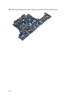
Replace the screw (M2.5x5) that secures the USB Type-C port bracket to the
system board.
7
Slide the I/O-board cable into the connector on the I/O-board and close the
latch to secure the cable.
8
Adhere the tape that secures the I/O-board cable to the I/O board.
9
Slide the touchpad cable into the connector on the system board and close
the latch to secure the cable.
10
Insert the RGB per key keyboard cable (optional) into the connector and
press down the latch to secure the cable.
11
Connect the speaker cable to the system board.
12
Connect the power-adapter port cable to the system board.
13
Route the coin-cell battery through the routing channel and adhere the tape
to secure the cable.
74