Dell Alienware 17 R5 Service Manual - Page 98
Replace the six screws M2.5x5 that secure the display assembly to the palm
 |
View all Dell Alienware 17 R5 manuals
Add to My Manuals
Save this manual to your list of manuals |
Page 98 highlights
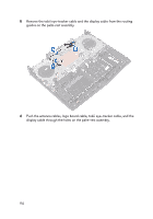
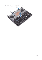
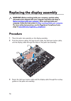
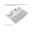
6 Replace the six screws (M2.5x5) that secure the display assembly to the palmrest assembly. Post-requisites 1 Replace the power-adapter port. 2 Follow the procedure from step 2 to step 18 in "Replacing the system board". 3 Replace the computer base. 4 Replace the rear-I/O cover. 5 Replace the memory modules. 6 Replace the solid-state drive. 7 Replace the wireless card. 8 Follow the procedure from step 4 to step 7 in "Replacing the hard drive". 9 Replace the base cover. 98
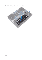
-
 1
1 -
2
-
3
-
4
-
5
-
6
-
7
-
8
-
9
-
10
-
11
-
12
-
13
-
14
-
15
-
16
-
17
-
18
-
19
-
20
-
21
-
22
-
23
-
24
-
25
-
26
-
27
-
28
-
29
-
30
-
31
-
32
-
33
-
34
-
35
-
36
-
37
-
38
-
39
-
40
-
41
-
42
-
43
-
44
-
45
-
46
-
47
-
48
-
49
-
50
-
51
-
52
-
53
-
54
-
55
-
56
-
57
-
58
-
59
-
60
-
61
-
62
-
63
-
64
-
65
-
66
-
67
-
68
-
69
-
70
-
71
-
72
-
73
-
74
-
75
-
76
-
77
-
78
-
79
-
80
-
81
-
82
-
83
-
84
-
85
-
86
-
87
-
88
-
89
-
90
-
91
-
92
-
 93
93 -
 94
94 -
 95
95 -
 96
96 -
 97
97 -
 98
98 -
 99
99 -
 100
100 -
 101
101 -
 102
102 -
 103
103 -
104
-
105
-
106
-
107
-
108
-
109
-
110
-
111
-
112
-
113
-
114
-
115
-
116
-
117
-
118
-
119
-
120
-
121
-
122
-
123
-
124
-
125
-
126
-
127
-
128
-
129
-
130
-
131
-
132
-
133
-
134
-
135
-
136
-
137
-
138
-
139
-
140
-
141
-
142
-
143
-
144
-
145
-
146
-
147
-
148
-
149
-
150
-
151
 |
 |
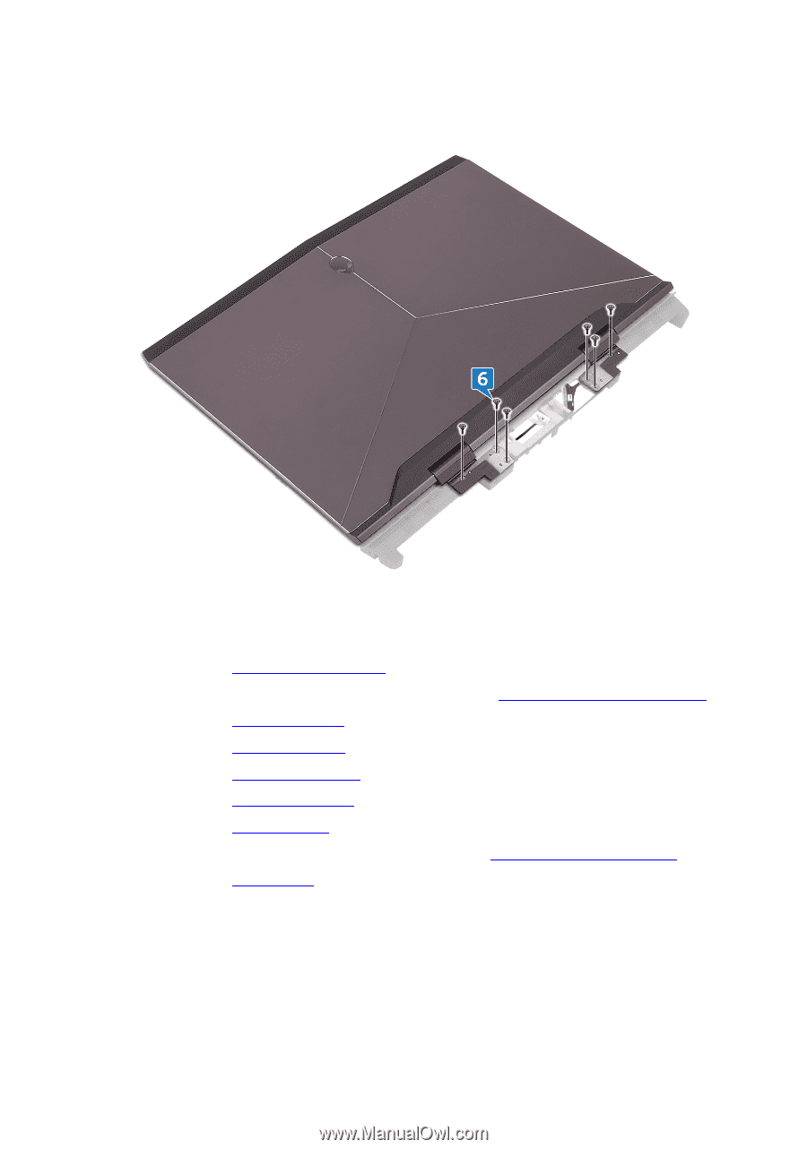
6
Replace the six screws (M2.5x5) that secure the display assembly to the palm-
rest assembly.
Post-requisites
1
Replace the
power-adapter port
.
2
Follow the procedure from step 2 to step 18 in “
Replacing the system board
”.
3
Replace the
computer base
.
4
Replace the
rear-I/O cover
.
5
Replace the
memory modules
.
6
Replace the
solid-state drive
.
7
Replace the
wireless card
.
8
Follow the procedure from step 4 to step 7 in “
Replacing the hard drive
”.
9
Replace the
base cover
.
98