Dell Alienware M18x R2 Owner's Manual - Page 81
Replacing the Processor Module, Procedure, Postrequisites
 |
View all Dell Alienware M18x R2 manuals
Add to My Manuals
Save this manual to your list of manuals |
Page 81 highlights
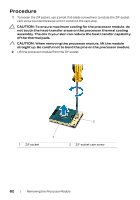
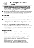
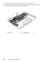
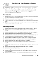
46 Replacing the Processor Module WARNING: Before working inside your computer, read the safety information that shipped with your computer and follow the steps in "Before You Begin" on page 9. For additional safety best practices information, see the Regulatory Compliance Homepage at dell.com/regulatory_compliance. NOTE: If a new processor module is installed, you will receive a new processor heatsink assembly, which will include an affixed thermal pad, or you will receive a new thermal pad along with documentation to illustrate proper installation. Procedure 1 Align the pin-1 corner of the processor module with the pin-1 corner of the ZIF socket, then place the processor module. NOTE: The pin-1 corner of the processor module has a triangle that aligns with the triangle on the pin-1 corner of the ZIF socket. When the processor module is properly seated, all four corners are aligned at the same height. If one or more corners of the module are higher than the others, the module is not seated properly. CAUTION: To avoid damage to the processor module, hold the screwdriver perpendicular to the processor module when turning the cam screw. 2 Tighten the ZIF socket by turning the cam screw clockwise to secure the processor module to the system board. Postrequisites 1 Replace the processor heat-sink. See ."Replacing the Processor Heat-Sink" on page 80. 2 Follow the instructions from step 2 to step 5 in Replacing the Palm Rest. 3 Replace the dispaly assembly. See "Replacing the Display Assembly" on page 48. 4 Replace the macro keyboard. See "Replacing the Macro Keyboard" on page 38. 5 Replace the keyboard. See "Replacing the Keyboard" on page 35. 6 Replace the center control cover. See "Replacing the Center Control Cover" on page 29. 7 Replace the base cover. See "Replacing the Base Cover" on page 15. 8 Replace the battery pack. See "Replacing the Battery Pack" on page 13. 9 Follow the instructions in "After Working Inside Your Computer" on page 11. Replacing the Processor Module | 83
-
 1
1 -
2
-
3
-
4
-
5
-
6
-
7
-
8
-
9
-
10
-
11
-
12
-
13
-
14
-
15
-
16
-
17
-
18
-
19
-
20
-
21
-
22
-
23
-
24
-
25
-
26
-
27
-
28
-
29
-
30
-
31
-
32
-
33
-
34
-
35
-
36
-
37
-
38
-
39
-
40
-
41
-
42
-
43
-
44
-
45
-
46
-
47
-
48
-
49
-
50
-
51
-
52
-
53
-
54
-
55
-
56
-
57
-
58
-
59
-
60
-
61
-
62
-
63
-
64
-
65
-
66
-
67
-
68
-
69
-
70
-
71
-
72
-
73
-
74
-
75
-
 76
76 -
 77
77 -
 78
78 -
 79
79 -
 80
80 -
 81
81 -
 82
82 -
 83
83 -
 84
84 -
 85
85 -
 86
86 -
87
-
88
-
89
-
90
-
91
-
92
-
93
-
94
-
95
-
96
-
97
-
98
-
99
-
100
-
101
-
102
-
103
 |
 |