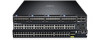
Dell Force10 S5000 Getting Started Guide - Page 11
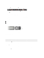
Installation, QSFP+ Port LEDs, Table 5. 40GbE Port/Module LEDs
 |
View all Dell Force10 S5000 manuals
Add to My Manuals
Save this manual to your list of manuals |
Page 11 highlights
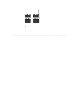
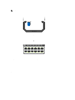
Figure 8. QSFP+ Port LEDs 1. Port link/activity LED Table 5. 40GbE Port/Module LEDs Label Port link/activity LED LED Color/Display • Off • Green solid • Green blinking Description • No link or interface disabled • Link present and interface enabled • Port has activity Installation Before installing the switch, verify that you meet these guidelines: • Enough clearance to the front of the switch so you can read the LEDs. • AC/DC power cord reaches from the power outlet to the Utility-panel connector. • Switch is rack-mounted before you install the power supply modules. • Cabling is away from sources of electrical noise, such as radios, power lines, and fluorescent lighting. Make sure that the cabling is safely away from other devices that might damage the cables. If needed, allow one RU space between devices to provide room for cabling. • Airflow around the switch and through the vents is unrestricted. • Temperature around the unit does not exceed 104°F (40°C). If the switch is in a closed or multirack assembly, the temperature might be higher than normal room temperature. • Humidity around the switch does not exceed 85 percent. • Altitude at the installation site is below 6600 feet. • Switch is installed in an environment as free as possible from dust and foreign conductive material (such as metal flakes from construction activities). Cooling mechanisms, such as fans and blowers in the switch, can draw dust and other particles causing contaminant buildup inside the chassis, which can result in system malfunction. 11
-
 1
1 -
2
-
3
-
4
-
5
-
 6
6 -
 7
7 -
 8
8 -
 9
9 -
 10
10 -
 11
11 -
 12
12 -
 13
13 -
 14
14 -
 15
15 -
 16
16 -
17
-
18
-
19
-
20
-
21
-
22
-
23
-
24
-
25
-
26
-
27
-
28
-
29
-
30
-
31
-
32
-
33
-
34
-
35
-
36
 |
 |
