Dell Force10 S5000 Getting Started Guide - Page 7
Port Numbering Convention, System Status, FTOS Command Line Reference Guide, FTOS Configuration - configuration guide
 |
View all Dell Force10 S5000 manuals
Add to My Manuals
Save this manual to your list of manuals |
Page 7 highlights
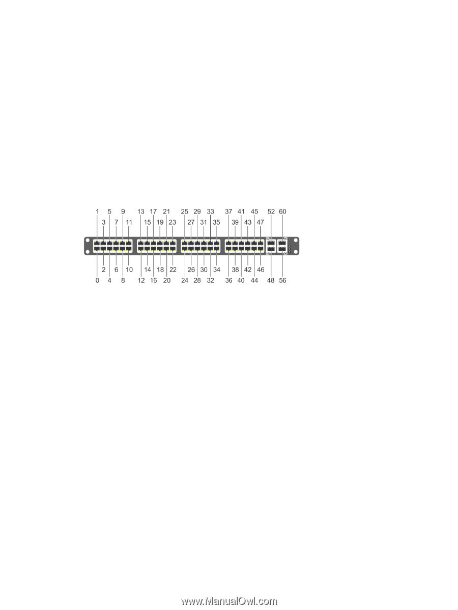
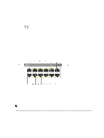
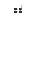
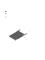
PSUs are field replaceable. To ensure power redundancy and adequate cooling, install two power supplies in the switch. When running with full redundancy (two PSUs installed and running), you can remove and replace one PSU while the other PSU is running without disrupting traffic. Fans The S5000 supports two fan trays with airflow directions from I/O to Utility or Utility to I/O. Do not mix I/O to Utility and Utility to I/O airflows in a single S5000 chassis. All fans and PSUs in a configuration must be in the same airflow direction. If you create a mixed airflow configuration, the software notifies you of the invalid configuration. The fans must be installed at the customer site. Port Numbering Convention Even-numbered ports are at the bottom of the I/O panel and for modules odd-numbered ports are at the top of the I/O panel. Figure 4. Port Numbering The previous figure shows the fixed four 40GbE data ports (ports 48, 52, 56, and 60) and the four slots for pluggable modules on the S5000 I/ O panel. You can also use the 40GbE ports in 4 × 10GbE mode. The S5000 supports the following possible modules: • 12-Port Ethernet Module (1G/10G speeds) (slot 0, 1, 2, or 3) • 12-Port Fibre Channel Module (2G/4G/8G speeds) (slot 0) The valid slot numbers are stack-unit numbers (from 0 to 11). The valid port numbers for each interface type are: • 1GbE: Ports 0 to 47 • 10GbE: Ports 0 to 63 • 40GbE: Ports 48, 52, 56, and 60 • Fibre Channel: Ports 0 to 11 • Management: Port 0 System Status You can view S5000 status information in several ways, including LEDs and through the CLI show commands and with simple network management protocol (SNMP). For more information about these options, refer to the FTOS Command Line Reference Guide and FTOS Configuration Guide for the S5000 Switch. As shown in the following figure, the S5000 includes LED displays on the I/O and Utility side of the chassis. When the S5000 powers up or reloads, the status LED on the power supplies are solid green. 7
-
 1
1 -
 2
2 -
 3
3 -
 4
4 -
 5
5 -
 6
6 -
 7
7 -
 8
8 -
 9
9 -
 10
10 -
 11
11 -
 12
12 -
13
-
14
-
15
-
16
-
17
-
18
-
19
-
20
-
21
-
22
-
23
-
24
-
25
-
26
-
27
-
28
-
29
-
30
-
31
-
32
-
33
-
34
-
35
-
36
 |
 |