Dell Force10 S5000 Getting Started Guide - Page 5
Hardware Installation Overview, Hardware Overview, I/O Panel
 |
View all Dell Force10 S5000 manuals
Add to My Manuals
Save this manual to your list of manuals |
Page 5 highlights
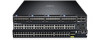
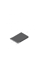
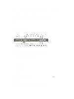
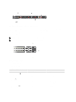
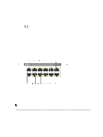
3. Four 40GbE QSFP+ ports (each port ALSO supports 4 × 10GbE mode) Hardware Installation Overview To install the S5000, follow these steps: 1. Attach the mounting brackets. 2. Install the S5000 chassis into a 4-post rack or cabinet. 3. Ground the rack. 4. Install the Ethernet and/or Fibre Channel modules (Fibre Channel module must be installed only in slot 0). 5. Install the power supplies. 6. Secure the power cables. 7. Install the fan modules. 8. Install the SFP+ and QSFP+ optics. 9. Supply power and power up the system. Hardware Overview This section contains information about device characteristics and modular hardware configurations for the S5000. The S5000 has the following physical dimensions: • Height: 1.71 inches (43.5 mm) • Width: 17.4 inches (441.9 mm) • Depth: 28 inches (711.2 mm) The S5000 has a chassis design with 640Gbps switching bandwidth. The system also provides one DB9 RS-232 console port with YOST RJ-45 pinout and a dedicated Ethernet service port for out-of-band (OOB) management functions. I/O Panel All fixed data ports (4 × 40GbE quad small form-factor pluggable plus [QSFP+] ports) and the four slots for pluggable modules are on the I/O panel. The I/O panel includes: • Pluggable Modules - 12-Port Ethernet Module (1G/10G speeds) - 12-Port Fibre Channel Module (2G/4G/8G speeds) • 4 × 40GbE QSFP+ Ports and light emitting diodes (LEDs) 5
-
 1
1 -
 2
2 -
 3
3 -
 4
4 -
 5
5 -
 6
6 -
 7
7 -
 8
8 -
 9
9 -
 10
10 -
 11
11 -
12
-
13
-
14
-
15
-
16
-
17
-
18
-
19
-
20
-
21
-
22
-
23
-
24
-
25
-
26
-
27
-
28
-
29
-
30
-
31
-
32
-
33
-
34
-
35
-
36
 |
 |
