Dell Force10 S5000 Getting Started Guide - Page 4
Important Points Before You Continue, Getting Started Guide, Safety and Regulatory Information
 |
View all Dell Force10 S5000 manuals
Add to My Manuals
Save this manual to your list of manuals |
Page 4 highlights
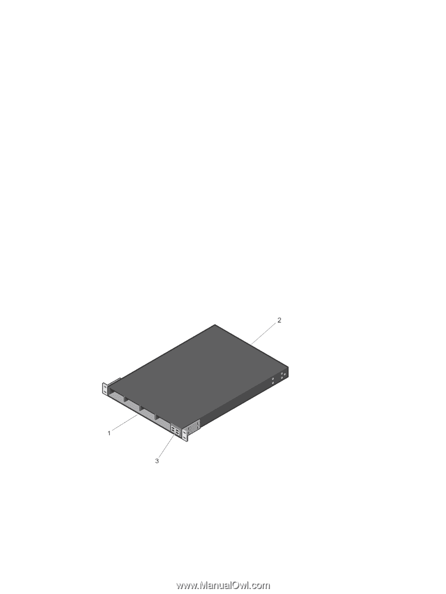
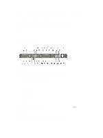
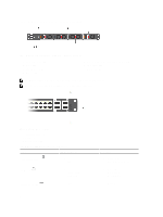
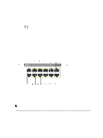
• One rail kit (#1 and #2 Phillips screwdrivers required) • Screws for rack installation • Two to Four I/O Modules (according to order) • Two Blanks • One RJ-45 to DB-9 female cable • Two AC or DC power cords for AC or DC units (country/region specific) • Getting Started Guide • Safety and Regulatory Information • Warranty and Support Information • Software License Agreement 1. Place the container on a clean, flat surface and cut all straps securing the container. 2. Open the container or remove the container top. 3. Carefully remove all components from the container and place it on a secure and clean surface. 4. Remove all packing material. 5. Inspect the switch and accessories for damage. Important Points Before You Continue • Identify the I/O and Utility panel on the chassis. The I/O panel has four fixed 40GbE ports on the right side of the panel, refer to Figure 1. The Utility panel has the power supply slots, LEDs, and USB slots on the left side of the panel, refer to Figure 3. • Identify slots 0, 1, 2, and 3 on the I/O panel, refer to Figure 2. You can insert a Fibre Channel module only in slot 0. You can install the Ethernet modules in slots 0, 1, 2, and 3. • Identify slots 0, 1, 2, and 3 on the Utility panel, refer to Figure 3. You can insert Power supply units (PSUs) only in slots 0 and 3. You can insert the Fan modules in any of the slots. Figure 1. S5000 I/O and Utility Panels 1. I/O panel 2. Utility panel 4
-
 1
1 -
 2
2 -
 3
3 -
 4
4 -
 5
5 -
 6
6 -
 7
7 -
 8
8 -
 9
9 -
 10
10 -
11
-
12
-
13
-
14
-
15
-
16
-
17
-
18
-
19
-
20
-
21
-
22
-
23
-
24
-
25
-
26
-
27
-
28
-
29
-
30
-
31
-
32
-
33
-
34
-
35
-
36
 |
 |