Dell Force10 S5000 Getting Started Guide - Page 15
Installing an Ethernet Module, Port Number
 |
View all Dell Force10 S5000 manuals
Add to My Manuals
Save this manual to your list of manuals |
Page 15 highlights
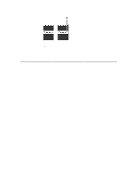
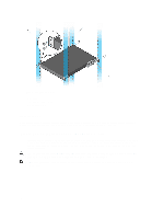
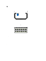
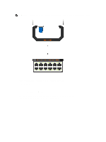
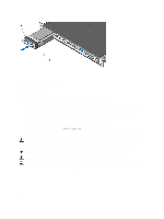
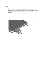
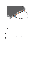
NOTE: A blue color release latch indicates that the Ethernet module does not support hot swapping during switch operations. Instead, you must power down the switch before removing and replacing an Ethernet module. A red color release latch indicates that the Ethernet module supports hot swapping during switch operations. Figure 11. Part name and Port number on the Ethernet Module Handle 1. Part Name 2. Port Number Installing an Ethernet Module 1. Use the grab handle on the Ethernet module to slide it into the switch module slot. 2. Connect any network interface cables to the attached module. 15
-
 1
1 -
2
-
3
-
4
-
5
-
6
-
7
-
8
-
9
-
 10
10 -
 11
11 -
 12
12 -
 13
13 -
 14
14 -
 15
15 -
 16
16 -
 17
17 -
 18
18 -
 19
19 -
 20
20 -
21
-
22
-
23
-
24
-
25
-
26
-
27
-
28
-
29
-
30
-
31
-
32
-
33
-
34
-
35
-
36
 |
 |

NOTE:
A blue color release latch indicates that the Ethernet module does not support hot swapping during switch
operations. Instead, you must power down the switch before removing and replacing an Ethernet module. A red
color release latch indicates that the Ethernet module supports hot swapping during switch operations.
Figure 11. Part name and Port number on the Ethernet Module Handle
1. Part Name
2. Port Number
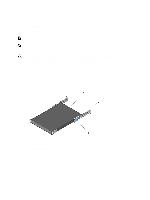
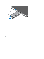
Installing an Ethernet Module
1.
Use the grab handle on the Ethernet module to slide it into the switch module slot.
2.
Connect any network interface cables to the attached module.
15