Dell Force10 S5000 Getting Started Guide - Page 24
Securing Power Cables, DC Power and Return Cables
 |
View all Dell Force10 S5000 manuals
Add to My Manuals
Save this manual to your list of manuals |
Page 24 highlights
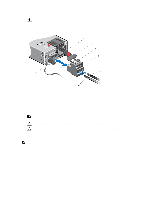
Figure 20. Installing the Ferrite Bead for DC Power and Return Cables 1. Ferrite Bead 2. DC Power and Return Cables 3. Leave approximately 4 to 5 inches of the DC power and return cables end protruding from the ferrite. 4. Snap the ferrite bead shut. Securing Power Cables 1. Bend the system power cables, as shown in the following illustration, and attach to the cable clasp. Figure 21. Securing Power Cables 2. Plug the other end of the power cables into a grounded electrical outlet or a separate power source such as an uninterruptible power supply (UPS) or a power distribution unit (PDU). NOTE: For better performance, ensure that the system is connected to a stand-alone power source with stable power supply. 24
-
 1
1 -
2
-
3
-
4
-
5
-
6
-
7
-
8
-
9
-
10
-
11
-
12
-
13
-
14
-
15
-
16
-
17
-
18
-
 19
19 -
 20
20 -
 21
21 -
 22
22 -
 23
23 -
 24
24 -
 25
25 -
 26
26 -
 27
27 -
 28
28 -
 29
29 -
30
-
31
-
32
-
33
-
34
-
35
-
36
 |
 |

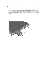
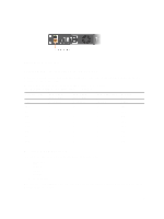
Figure 20. Installing the Ferrite Bead for DC Power and Return Cables
1. Ferrite Bead
2. DC Power and Return Cables
3.
Leave approximately 4 to 5 inches of the DC power and return cables end protruding from the ferrite.
4.
Snap the ferrite bead shut.
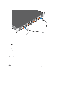
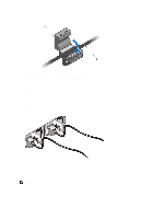
Securing Power Cables
1.
Bend the system power cables, as shown in the following illustration, and attach to the cable clasp.
Figure 21. Securing Power Cables
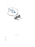
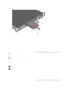
2.
Plug the other end of the power cables into a grounded electrical outlet or a separate power source such as an
uninterruptible power supply (UPS) or a power distribution unit (PDU).
NOTE:
For better performance, ensure that the system is connected to a stand-alone power source with stable
power supply.
24