Dell Force10 S55T Quick Start Guide - Page 12
AC Power, As soon as the cable is connected between the system and the power source, - s55 stacking module
 |
View all Dell Force10 S55T manuals
Add to My Manuals
Save this manual to your list of manuals |
Page 12 highlights
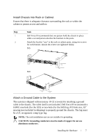
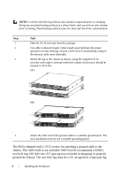
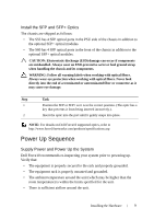
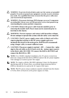
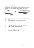
• The input circuits are correctly sized for the loads and that sufficient overcurrent protection devices are used. • All protective covers are in place. • Blank panels are installed if optional modules are not installed. • Blank panels are installed if redundant power supplies are not installed on the S55. NOTE: A US AC power cable is included in the shipping container for powering up an AC power supply. All other power cables must be ordered separately. CAUTION: Electrostatic discharge (ESD) damage can occur if components are mishandled. Always wear an ESD-preventive wrist or heel ground strap when handling the system and its components. When the chassis powers up, the fans immediately come on at high speed. The fan speed slows as the system boots up. The PWR LED blinks until the boot-up sequence is complete. When the boot up is complete the PWD LED is steadily lit. The Stack ID LED displays a digit to show the position of the unit in a stacking chain. For a single chassis, a 0 displays. AC Power Connect the plug to each AC receptacle, making sure that the power cord is secure. As soon as the cable is connected between the system and the power source, the chassis is powered-up; there is no on/off switch. DC Power To connect the chassis to the DC power source, follow the steps below: Step Task S55 Task S60 1 Connect the plug to each DC Remove the small plastic cover from receptacle, making sure that the the DC connectors. power cord is secure. 10 Installing the Hardware
-
 1
1 -
2
-
3
-
4
-
5
-
6
-
 7
7 -
 8
8 -
 9
9 -
 10
10 -
 11
11 -
 12
12 -
 13
13 -
 14
14 -
 15
15 -
 16
16 -
 17
17 -
18
-
19
-
20
-
21
-
22
-
23
-
24
-
25
-
26
-
27
-
28
 |
 |