Dell GX280DT User Guide - Page 159
For more information, see System Setup Options.
 |
UPC - 851846002006
View all Dell GX280DT manuals
Add to My Manuals
Save this manual to your list of manuals |
Page 159 highlights
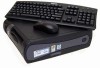
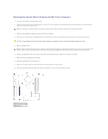
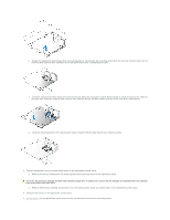
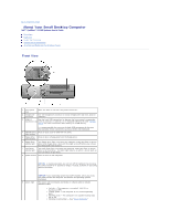
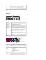
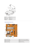
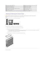
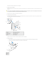
10 front-panel door To exit from a power-saving state, press the power button or use the keyboard or the mouse if it is configured as a wake device in the Windows Device Manager. For more information about sleep states and exiting from a power-saving state, see "Power Management." See "Diagnostic Lights" for a description of light codes that can help you troubleshoot problems with your computer. Open the door to use the front-panel connectors. Back View 1 back panel connectors 2 security cable slot 3 padlock ring 4 card slots 5 voltage selection switch (may not be available on all computers) Plug serial, USB, and other devices into the appropriate connector. Use a security cable with the slot to help secure your computer. Insert a padlock to lock the computer cover. Access connectors for any installed PCI and PCI Express cards. Your computer is equipped with either an auto-sensing voltage selector or a manual voltage selection switch. Computers with an auto-sensing voltage selector do not have a voltage selection switch on the back panel and can automatically detect the correct operating voltage. To help avoid damaging a computer with a manual voltage selection switch, set the switch for the voltage that most closely matches the AC power available in your location. 6 power connector NOTICE: The voltage selection switch must be set to the 115-V position even though the AC power available in Japan is 100 V. Also, ensure that your monitor and attached devices are electrically rated to operate with the AC power available in your location. Insert the power cable. 1 serial connector Connect a serial device, such as a handheld device, to the serial port. The default designations are COM1 for serial connector 1 and COM2 for serial connector 2. 2 link integrity light For more information, see "System Setup Options." l Green - A good connection exists between a 10-Mbps network and the computer. l Orange - A good connection exists between a 100-Mbps network and the computer. l Yellow - A good connection exists between a 1-Gbps (or 1000Mbps) network and the computer. l Off - The computer is not detecting a physical connection to the network. 3 network adapter connector To attach your computer to a network or broadband device, connect one end of a network cable to either a network jack or your network or broadband device. Connect the other end of the network cable to the network adapter connector on the back panel of your computer. A click
-
 1
1 -
2
-
3
-
4
-
5
-
6
-
7
-
8
-
9
-
10
-
11
-
12
-
13
-
14
-
15
-
16
-
17
-
18
-
19
-
20
-
21
-
22
-
23
-
24
-
25
-
26
-
27
-
28
-
29
-
30
-
31
-
32
-
33
-
34
-
35
-
36
-
37
-
38
-
39
-
40
-
41
-
42
-
43
-
44
-
45
-
46
-
47
-
48
-
49
-
50
-
51
-
52
-
53
-
54
-
55
-
56
-
57
-
58
-
59
-
60
-
61
-
62
-
63
-
64
-
65
-
66
-
67
-
68
-
69
-
70
-
71
-
72
-
73
-
74
-
75
-
76
-
77
-
78
-
79
-
80
-
81
-
82
-
83
-
84
-
85
-
86
-
87
-
88
-
89
-
90
-
91
-
92
-
93
-
94
-
95
-
96
-
97
-
98
-
99
-
100
-
101
-
102
-
103
-
104
-
105
-
106
-
107
-
108
-
109
-
110
-
111
-
112
-
113
-
114
-
115
-
116
-
117
-
118
-
119
-
120
-
121
-
122
-
123
-
124
-
125
-
126
-
127
-
128
-
129
-
130
-
131
-
132
-
133
-
134
-
135
-
136
-
137
-
138
-
139
-
140
-
141
-
142
-
143
-
144
-
145
-
146
-
147
-
148
-
149
-
150
-
151
-
152
-
153
-
 154
154 -
 155
155 -
 156
156 -
 157
157 -
 158
158 -
 159
159 -
 160
160 -
 161
161 -
 162
162 -
 163
163 -
 164
164 -
165
-
166
-
167
-
168
-
169
-
170
-
171
-
172
-
173
-
174
-
175
-
176
-
177
-
178
-
179
-
180
-
181
-
182
-
183
-
184
-
185
-
186
-
187
-
188
-
189
-
190
-
191
-
192
-
193
-
194
-
195
-
196
-
197
-
198
-
199
-
200
-
201
-
202
-
203
-
204
-
205
-
206
-
207
-
208
-
209
-
210
-
211
-
212
-
213
-
214
-
215
-
216
-
217
-
218
-
219
-
220
-
221
-
222
-
223
-
224
-
225
-
226
-
227
-
228
-
229
-
230
-
231
-
232
-
233
-
234
-
235
-
236
-
237
-
238
-
239
-
240
-
241
-
242
-
243
-
244
-
245
-
246
-
247
-
248
-
249
-
250
-
251
-
252
-
253
-
254
-
255
-
256
-
257
-
258
-
259
-
260
-
261
-
262
-
263
-
264
-
265
-
266
-
267
-
268
-
269
-
270
-
271
-
272
-
273
-
274
-
275
-
276
-
277
-
278
-
279
-
280
-
281
-
282
-
283
-
284
-
285
-
286
-
287
-
288
-
289
 |
 |