Dell GX280DT User Guide - Page 32
Back View
 |
UPC - 851846002006
View all Dell GX280DT manuals
Add to My Manuals
Save this manual to your list of manuals |
Page 32 highlights
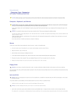
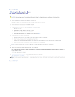
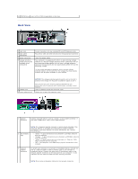
11 CD/DVD drive Insert a CD or DVD (if applicable) in this drive. Back View 1 card slots 2 back panel connectors 3 power connector 4 voltage selection switch (may not be available on all computers) Access connectors for any installed PCI and PCI Express cards. Plug serial, USB, and other devices into the appropriate connector. Insert the power cable. Your computer is equipped with either an auto-sensing voltage selector or a manual voltage selection switch. Computers with an auto-sensing voltage selector do not have a voltage selection switch on the back panel and can automatically detect the correct operating voltage. To help avoid damaging a computer with a manual voltage selection switch, set the switch for the voltage that most closely matches the AC power available in your location. 5 padlock ring 6 cover release latch NOTICE: The voltage selection switch must be set to the 115-V position even though the AC power available in Japan is 100 V. Also, ensure that your monitor and attached devices are electrically rated to operate with the AC power available in your location. Insert a padlock to lock the computer cover. Allows you to open the computer cover. 1 parallel connector Connect a parallel device, such as a printer, to the parallel connector. If you have a USB printer, plug it into a USB connector. 2 link integrity light NOTE: The integrated parallel connector is automatically disabled if the computer detects an installed card containing a parallel connector configured to the same address. For more information, see "System Setup Options." l Green - A good connection exists between a 10-Mbps network and the computer. l Orange - A good connection exists between a 100-Mbps network and the computer. l Yellow - A good connection exists between a 1-Gbps (or 1000Mbps) network and the computer. l Off - The computer is not detecting a physical connection to the network. 3 network adapter connector To attach your computer to a network or broadband device, connect one end of a network cable to either a network jack or your network or broadband device. Connect the other end of the network cable to the network adapter connector on the back panel of your computer. A click indicates that the network cable has been securely attached. NOTE: Do not plug a telephone cable into the network connector.
-
 1
1 -
2
-
3
-
4
-
5
-
6
-
7
-
8
-
9
-
10
-
11
-
12
-
13
-
14
-
15
-
16
-
17
-
18
-
19
-
20
-
21
-
22
-
23
-
24
-
25
-
26
-
 27
27 -
 28
28 -
 29
29 -
 30
30 -
 31
31 -
 32
32 -
 33
33 -
 34
34 -
 35
35 -
 36
36 -
 37
37 -
38
-
39
-
40
-
41
-
42
-
43
-
44
-
45
-
46
-
47
-
48
-
49
-
50
-
51
-
52
-
53
-
54
-
55
-
56
-
57
-
58
-
59
-
60
-
61
-
62
-
63
-
64
-
65
-
66
-
67
-
68
-
69
-
70
-
71
-
72
-
73
-
74
-
75
-
76
-
77
-
78
-
79
-
80
-
81
-
82
-
83
-
84
-
85
-
86
-
87
-
88
-
89
-
90
-
91
-
92
-
93
-
94
-
95
-
96
-
97
-
98
-
99
-
100
-
101
-
102
-
103
-
104
-
105
-
106
-
107
-
108
-
109
-
110
-
111
-
112
-
113
-
114
-
115
-
116
-
117
-
118
-
119
-
120
-
121
-
122
-
123
-
124
-
125
-
126
-
127
-
128
-
129
-
130
-
131
-
132
-
133
-
134
-
135
-
136
-
137
-
138
-
139
-
140
-
141
-
142
-
143
-
144
-
145
-
146
-
147
-
148
-
149
-
150
-
151
-
152
-
153
-
154
-
155
-
156
-
157
-
158
-
159
-
160
-
161
-
162
-
163
-
164
-
165
-
166
-
167
-
168
-
169
-
170
-
171
-
172
-
173
-
174
-
175
-
176
-
177
-
178
-
179
-
180
-
181
-
182
-
183
-
184
-
185
-
186
-
187
-
188
-
189
-
190
-
191
-
192
-
193
-
194
-
195
-
196
-
197
-
198
-
199
-
200
-
201
-
202
-
203
-
204
-
205
-
206
-
207
-
208
-
209
-
210
-
211
-
212
-
213
-
214
-
215
-
216
-
217
-
218
-
219
-
220
-
221
-
222
-
223
-
224
-
225
-
226
-
227
-
228
-
229
-
230
-
231
-
232
-
233
-
234
-
235
-
236
-
237
-
238
-
239
-
240
-
241
-
242
-
243
-
244
-
245
-
246
-
247
-
248
-
249
-
250
-
251
-
252
-
253
-
254
-
255
-
256
-
257
-
258
-
259
-
260
-
261
-
262
-
263
-
264
-
265
-
266
-
267
-
268
-
269
-
270
-
271
-
272
-
273
-
274
-
275
-
276
-
277
-
278
-
279
-
280
-
281
-
282
-
283
-
284
-
285
-
286
-
287
-
288
-
289
 |
 |