Dell Inspiron 13 N3010 Service Manual - Page 19
Display Bezel
 |
View all Dell Inspiron 13 N3010 manuals
Add to My Manuals
Save this manual to your list of manuals |
Page 19 highlights
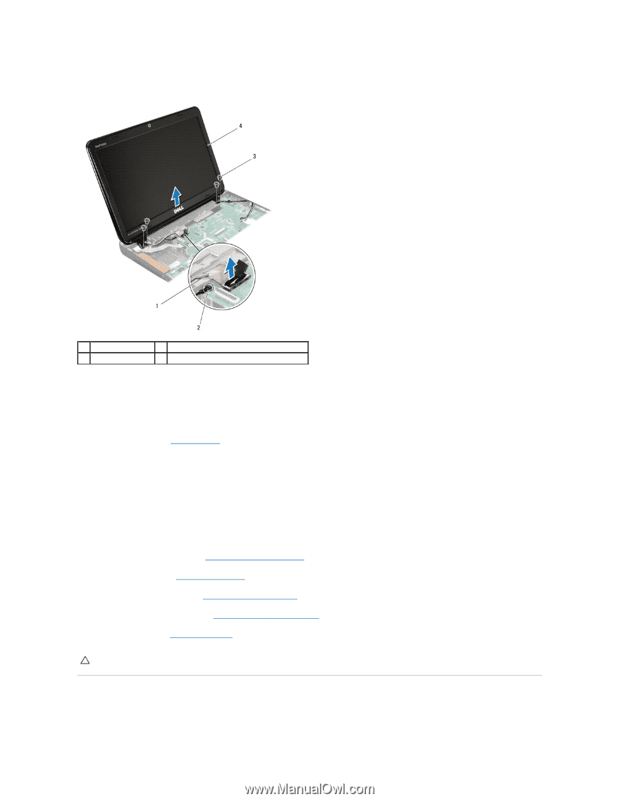
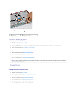
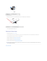
11. In sequential order (indicated on the display hinge), remove the four screws that secure the display assembly to the computer base. 1 display cable 3 screws (4) 2 display cable grounding screw 4 display assembly 12. Lift the display assembly off the computer. Replacing the Display Assembly 1. Follow the instructions in Before You Begin. 2. Place the display assembly in position. 3. In sequential order (indicated on the display hinge), replace the four screws that secure the display assembly to the computer base. 4. Connect the display cable to the connector on the system board. 5. Replace the display cable grounding screw. 6. Turn the computer over and replace the two screws that secure the display assembly to the computer base. 7. Replace the palm rest assembly (see Replacing the Palm Rest Assembly). 8. Replace the keyboard (see Replacing the Keyboard). 9. Replace the memory module(s) (see Replacing the Memory Module(s)). 10. Replace the memory-module cover (see Replacing the Memory-Module Cover). 11. Replace the battery (see Replacing the Battery). CAUTION: Before turning on the computer, replace all screws and ensure that no stray screws remain inside the computer. Failure to do so may result in damage to the computer. Display Bezel
-
 1
1 -
2
-
3
-
4
-
5
-
6
-
7
-
8
-
9
-
10
-
11
-
12
-
13
-
 14
14 -
 15
15 -
 16
16 -
 17
17 -
 18
18 -
 19
19 -
 20
20 -
 21
21 -
 22
22 -
 23
23 -
 24
24 -
25
-
26
-
27
-
28
-
29
-
30
-
31
-
32
-
33
-
34
-
35
-
36
-
37
-
38
-
39
-
40
-
41
-
42
-
43
-
44
-
45
-
46
-
47
-
48
 |
 |