Dell Inspiron 13 N3010 Service Manual - Page 44
Replacing the System Board
 |
View all Dell Inspiron 13 N3010 manuals
Add to My Manuals
Save this manual to your list of manuals |
Page 44 highlights
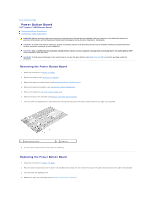
1 speaker cable connector 3 screws (3) 2 system board assembly 14. Remove the three screws that secure the system board assembly to the computer base. 15. Carefully ease the connectors on the system board assembly out of the slots in the computer base, and lift the system board assembly out of the computer base. 16. Turn the system board assembly over. 17. Remove the hard-drive assembly (see Removing the Hard Drive). 18. Remove the processor heat sink (see Removing the Processor Heat Sink). 19. Remove the processor module (see Removing the Processor Module). 20. Remove the coin-cell battery (see Removing the Coin-Cell Battery). 21. Remove the Mini-Card (see Removing the Mini-Card). Replacing the System Board 1. Follow the instructions in Before You Begin. 2. Replace the Mini-Card (see Replacing the Mini-Card). 3. Replace the coin-cell battery (see Replacing the Coin-Cell Battery). 4. Replace the processor module (see Replacing the Processor Module). 5. Replace the processor heat sink (see Replacing the Processor Heat Sink). 6. Replace the hard-drive assembly (see Replacing the Hard Drive). 7. Align the connectors on the system board assembly with the slots on the computer base and place it on the computer base. 8. Replace the three screws that secure the system board assembly to the computer base. 9. Connect the speaker cable to the connector on the system board. 10. Replace the VGA connector board (see Replacing the VGA Connector Board). 11. Replace the middle cover (see Replacing the Middle Cover). 12. Replace the processor heat sink fan (see Replacing the Processor Heat Sink Fan). 13. Replace the display assembly (see Replacing the Display Assembly).
-
 1
1 -
2
-
3
-
4
-
5
-
6
-
7
-
8
-
9
-
10
-
11
-
12
-
13
-
14
-
15
-
16
-
17
-
18
-
19
-
20
-
21
-
22
-
23
-
24
-
25
-
26
-
27
-
28
-
29
-
30
-
31
-
32
-
33
-
34
-
35
-
36
-
37
-
38
-
 39
39 -
 40
40 -
 41
41 -
 42
42 -
 43
43 -
 44
44 -
 45
45 -
 46
46 -
 47
47 -
 48
48
 |
 |
