Dell Inspiron 16 5630 Service Manual - Page 38
Installing the I/O board
 |
View all Dell Inspiron 16 5630 manuals
Add to My Manuals
Save this manual to your list of manuals |
Page 38 highlights
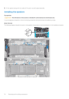
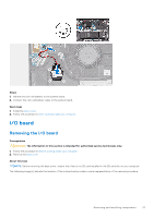
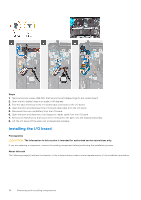
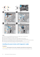
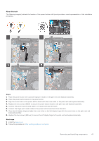
Steps 1. Remove the two screws (M2.5x5) that secure the left display hinge to the system board. 2. Open the left display hinge at an angle of 90 degrees. 3. Peel the tape that secures the I/O-board cable connector to the I/O board. 4. Open the latch and disconnect the I/O-board cable cable from the I/O board. 5. Disconnect the coin-cell battery from the I/O board. 6. Open the latch and disconnect the fingerprint-reader cable from the I/O board. 7. Remove the M2x3 screw that secures the I/O board to the palm-rest and keyboard assembly. 8. Lift the I/O board off the palm-rest and keyboard assembly. Installing the I/O board Prerequisites CAUTION: The information in this section is intended for authorized service technicians only. If you are replacing a component, remove the existing component before performing the installation process. About this task The following image(s) indicate the location of the io board and provides a visual representation of the installation procedure. 38 Removing and installing components
-
 1
1 -
2
-
3
-
4
-
5
-
6
-
7
-
8
-
9
-
10
-
11
-
12
-
13
-
14
-
15
-
16
-
17
-
18
-
19
-
20
-
21
-
22
-
23
-
24
-
25
-
26
-
27
-
28
-
29
-
30
-
31
-
32
-
 33
33 -
 34
34 -
 35
35 -
 36
36 -
 37
37 -
 38
38 -
 39
39 -
 40
40 -
 41
41 -
 42
42 -
 43
43 -
44
-
45
-
46
-
47
-
48
-
49
-
50
-
51
-
52
-
53
-
54
-
55
-
56
-
57
-
58
-
59
-
60
-
61
-
62
-
63
-
64
-
65
-
66
-
67
-
68
-
69
-
70
-
71
-
72
-
73
-
74
 |
 |
