Dell Inspiron 16 5630 Service Manual - Page 45
Display assembly, Removing the display assembly
 |
View all Dell Inspiron 16 5630 manuals
Add to My Manuals
Save this manual to your list of manuals |
Page 45 highlights
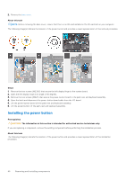
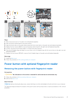
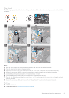
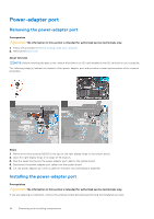
About this task The following image(s) indicate the location of the power-adapter port and provides a visual representation of the installation procedure. Steps 1. Place the power-adapter port into the slot on the palm-rest and keyboard assembly. 2. Connect the power-adapter port cable to the system board. 3. Adhere the tapes to secure the power-adapter port cable to the system board. 4. Close the right display hinge and align the screw holes on the right display hinge with the screw holes on the system board. 5. Replace the three screws (M2.5x5) to secure the right display hinge to the system board. Next steps 1. Install the base cover. 2. Follow the procedure in After working inside your computer. Display assembly Removing the display assembly Prerequisites CAUTION: The information in this section is intended for authorized service technicians only. 1. Follow the procedure in Before working inside your computer. 2. Remove the base cover. About this task NOTE: Before removing the base cover, ensure that there is no SD card installed in the SD card slot on your computer. The following image(s) indicate the location of the display assembly and provides a visual representation of the removal procedure. Removing and installing components 45
-
 1
1 -
2
-
3
-
4
-
5
-
6
-
7
-
8
-
9
-
10
-
11
-
12
-
13
-
14
-
15
-
16
-
17
-
18
-
19
-
20
-
21
-
22
-
23
-
24
-
25
-
26
-
27
-
28
-
29
-
30
-
31
-
32
-
33
-
34
-
35
-
36
-
37
-
38
-
39
-
 40
40 -
 41
41 -
 42
42 -
 43
43 -
 44
44 -
 45
45 -
 46
46 -
 47
47 -
 48
48 -
 49
49 -
 50
50 -
51
-
52
-
53
-
54
-
55
-
56
-
57
-
58
-
59
-
60
-
61
-
62
-
63
-
64
-
65
-
66
-
67
-
68
-
69
-
70
-
71
-
72
-
73
-
74
 |
 |
