Dell Inspiron 16 7610 Service Manual for computers with three fans - Page 41
Installing the heat sink
 |
View all Dell Inspiron 16 7610 manuals
Add to My Manuals
Save this manual to your list of manuals |
Page 41 highlights
Steps 1. In reverse sequential order (7>6>5>4>3>2>1) loosen the seven captive screws that secure the heat sink to the system board. 2. Lift the heat sink from the system board. Installing the heat sink Prerequisites If you are replacing a component, remove the existing component before performing the installation process. About this task NOTE: If either the system board or the heat sink is replaced, use the thermal grease provided in the kit to ensure that thermal conductivity is achieved. The following image(s) indicate the location of the heat sink and provides a visual representation of the installation procedure. Removing and installing components 41
-
 1
1 -
2
-
3
-
4
-
5
-
6
-
7
-
8
-
9
-
10
-
11
-
12
-
13
-
14
-
15
-
16
-
17
-
18
-
19
-
20
-
21
-
22
-
23
-
24
-
25
-
26
-
27
-
28
-
29
-
30
-
31
-
32
-
33
-
34
-
35
-
 36
36 -
 37
37 -
 38
38 -
 39
39 -
 40
40 -
 41
41 -
 42
42 -
 43
43 -
 44
44 -
 45
45 -
 46
46 -
47
-
48
-
49
-
50
-
51
-
52
-
53
-
54
-
55
-
56
-
57
-
58
-
59
-
60
-
61
-
62
-
63
-
64
-
65
-
66
-
67
-
68
-
69
-
70
-
71
-
72
-
73
-
74
-
75
-
76
-
77
-
78
-
79
 |
 |

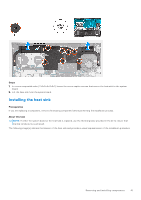
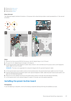
Steps
1.
In reverse sequential order (7>6>5>4>3>2>1) loosen the seven captive screws that secure the heat sink to the system
board.
2.
Lift the heat sink from the system board.
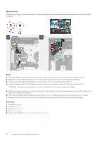
Installing the heat sink
Prerequisites
If you are replacing a component, remove the existing component before performing the installation process.
About this task
NOTE:
If either the system board or the heat sink is replaced, use the thermal grease provided in the kit to ensure that
thermal conductivity is achieved.
The following image(s) indicate the location of the heat sink and provides a visual representation of the installation procedure.
Removing and installing components
41