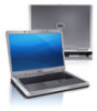
Dell Inspiron 3200 Service Manual - Page 94
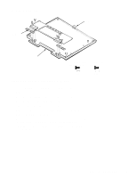
Remove front bezel screws F1, F2, F3, and F4., of the front bezel out to the side
 |
View all Dell Inspiron 3200 manuals
Add to My Manuals
Save this manual to your list of manuals |
Page 94 highlights
3. Remove front bezel screws F1, F2, F3, and F4. 4. Separate the front bezel from the back cover. With the bottom of the LCD assembly facing you (cables end), insert your fingertips between the LCD panel and the front bezel. Start in the center of the bezel and work out to the corners. With a peel-back-and-push motion, separate the front bezel from the hidden tabs on the back cover. Do not put pressure on the LCD panel with your knuckles; microscopic fractures in the panel could result. Separate the bottom first and then proceed to each side, leaving the top of the assembly until last. When the bottom and sides have been released from the hidden tabs, proceed to the left corner. Lift the corner of the front bezel out to the side, until the hidden corner tab is freed. Repeat the procedure for the other corner, and lift up on the front bezel to release it from the back cover. Lift the back cover over the latch. When replacing the bezel, ensure that the LCD flex cable and the inverter cable are routed correctly through the openings in the back cover and are not pinched. 4-58 Dell Inspiron 3000 Series Service Manual
-
 1
1 -
2
-
3
-
4
-
5
-
6
-
7
-
8
-
9
-
10
-
11
-
12
-
13
-
14
-
15
-
16
-
17
-
18
-
19
-
20
-
21
-
22
-
23
-
24
-
25
-
26
-
27
-
28
-
29
-
30
-
31
-
32
-
33
-
34
-
35
-
36
-
37
-
38
-
39
-
40
-
41
-
42
-
43
-
44
-
45
-
46
-
47
-
48
-
49
-
50
-
51
-
52
-
53
-
54
-
55
-
56
-
57
-
58
-
59
-
60
-
61
-
62
-
63
-
64
-
65
-
66
-
67
-
68
-
69
-
70
-
71
-
72
-
73
-
74
-
75
-
76
-
77
-
78
-
79
-
80
-
81
-
82
-
83
-
84
-
85
-
86
-
87
-
88
-
 89
89 -
 90
90 -
 91
91 -
 92
92 -
 93
93 -
 94
94 -
 95
95 -
 96
96 -
 97
97 -
 98
98 -
 99
99 -
100
-
101
-
102
-
103
-
104
-
105
-
106
-
107
-
108
-
109
-
110
-
111
-
112
 |
 |
