Dell Inspiron Mini 12 1210 Inspiron Mini 12 Service Manual - Page 10
Replacing the 2-in-1 Processor and Memory Board
 |
View all Dell Inspiron Mini 12 1210 manuals
Add to My Manuals
Save this manual to your list of manuals |
Page 10 highlights
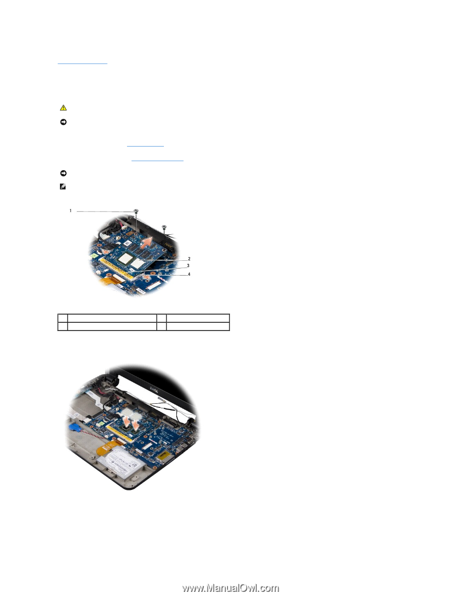
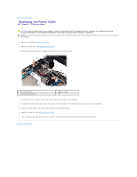
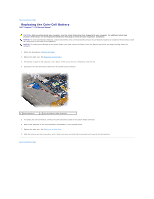
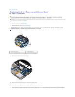
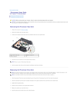
Back to Contents Page Replacing the 2-in-1 Processor and Memory Board Dell™ Inspiron™ 1210 Service Manual CAUTION: Before working inside your computer, read the safety information that shipped with your computer. For additional safety best practices information, see the Regulatory Compliance Homepage at www.dell.com/regulatory_compliance. NOTICE: To avoid electrostatic discharge, ground yourself by using a wrist grounding strap or by periodically touching an unpainted metal surface (such as a connector on the back of the computer). 1. Follow the instructions in Before You Begin. 2. Remove the palm rest. See Replacing the Palm Rest. NOTICE: When the 2-in-1 memory and processor board is not in the computer, store it in protective antistatic packaging (see "Protecting Against Electrostatic Discharge" in the safety instructions that shipped with your computer). NOTE: The thermal pads may stick to the bottom of the palm rest. Remove the thermal pads from the bottom of the palm rest. 1 M2x4-mm screw (2) 3 tab in the connector slot 2 thermal pads (2) 4 securing clips (2) 3. Remove the two thermal pads on the processor. 4. Place the thermal pads on the new 2-in-1 memory and processor board. 5. Remove the two M2x4-mm screws that secure the 2-in-1 memory and processor board. 6. Use your fingertips to carefully spread apart the securing clips on either side of 2-in-1 memory and processor board connector until the board pops up.
-
 1
1 -
2
-
3
-
4
-
 5
5 -
 6
6 -
 7
7 -
 8
8 -
 9
9 -
 10
10 -
 11
11 -
 12
12 -
 13
13 -
 14
14 -
 15
15 -
16
-
17
-
18
-
19
-
20
-
21
-
22
-
23
-
24
-
25
-
26
-
27
-
28
-
29
-
30
-
31
-
32
-
33
-
34
-
35
-
36
-
37
-
38
 |
 |