Dell Inspiron Mini 12 1210 Inspiron Mini 12 Service Manual - Page 17
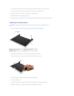
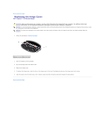
Replacing the Display Bezel, Back to Contents
 |
View all Dell Inspiron Mini 12 1210 manuals
Add to My Manuals
Save this manual to your list of manuals |
Page 17 highlights
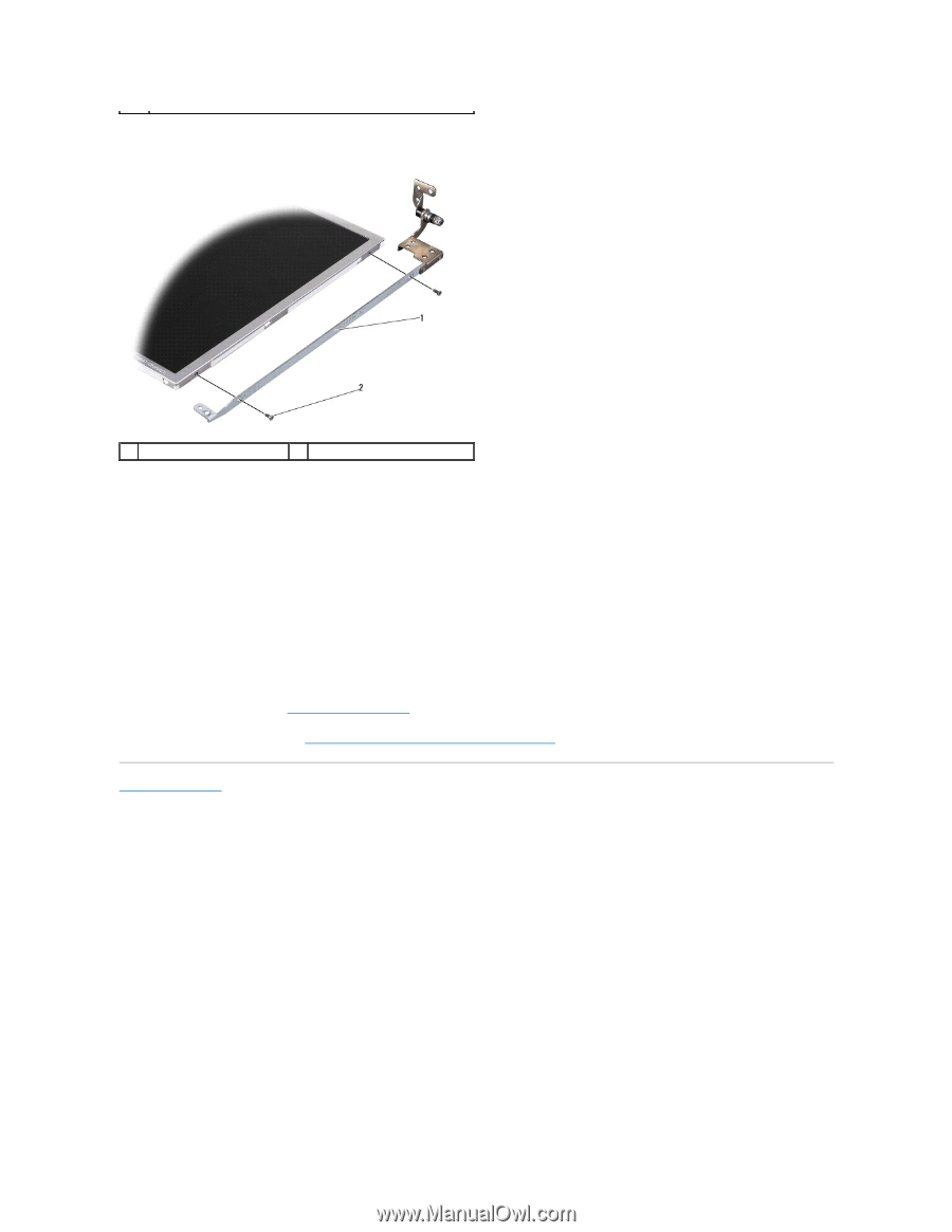
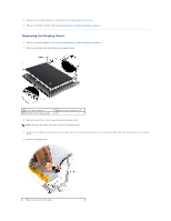
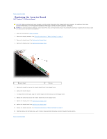
6. Remove the 2-in-1 camera and LVDS cable. 1 display panel bracket 2 M2 x 2.5-mm screws (4) 7. Remove the four M2 x 2.5-mm screws (two on each side) that secure the display panel bracket to the display panel. 8. To replace the display panel, align the display panel bracket with the display panel. 9. Replace the four M2 x 2.5-mm screws that secure the display panel brackets to each side of the display panel. 10. Replace the 2-in-1 camera and LVDS cable. 11. Align the display panel with the display panel frame and replace the six M2.5 x 3-mm screws. 12. Route the cables back through their routing channels. 13. Replace the cables from the connectors on either side of the inverter board and the 2-in-1 camera and LVDS cable from the connector on the camera board. 14. Replace the display bezel (see Replacing the Display Bezel). 15. Replace the display assembly (see Follow the instructions in "Before You Begin" on page 9.). Back to Contents Page
-
 1
1 -
2
-
3
-
4
-
5
-
6
-
7
-
8
-
9
-
10
-
11
-
 12
12 -
 13
13 -
 14
14 -
 15
15 -
 16
16 -
 17
17 -
 18
18 -
 19
19 -
 20
20 -
 21
21 -
 22
22 -
23
-
24
-
25
-
26
-
27
-
28
-
29
-
30
-
31
-
32
-
33
-
34
-
35
-
36
-
37
-
38
 |
 |