Dell Inspiron Mini 12 1210 Inspiron Mini 12 Service Manual - Page 35
Replacing the System Board
 |
View all Dell Inspiron Mini 12 1210 manuals
Add to My Manuals
Save this manual to your list of manuals |
Page 35 highlights
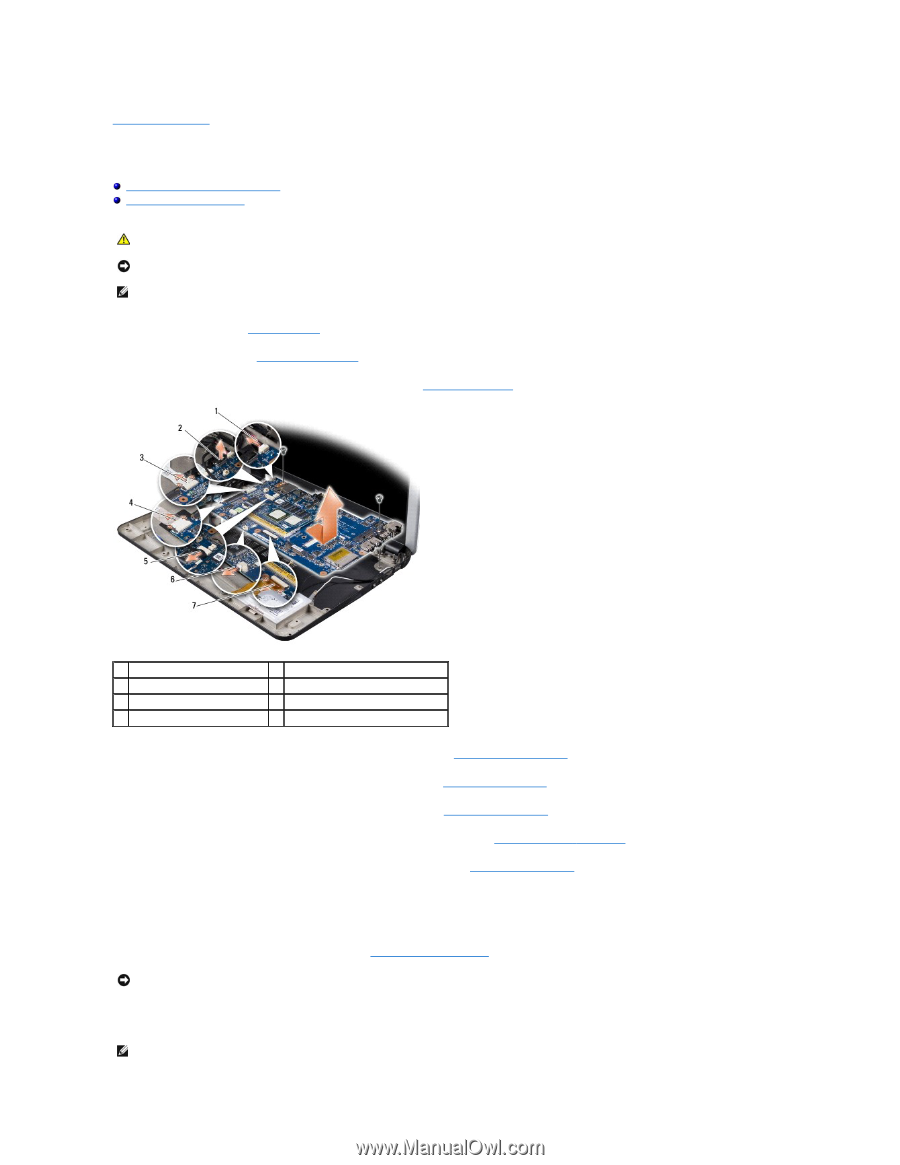
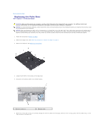
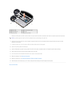
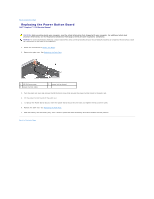
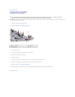
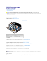
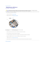
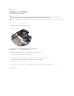
Back to Contents Page Replacing the System Board Dell™ Inspiron™ 1210 Service Manual Entering the Service Tag in the BIOS Setting the Keyboard Matrix CAUTION: Before working inside your computer, read the safety information that shipped with your computer. For additional safety best practices information, see the Regulatory Compliance Homepage at www.dell.com/regulatory_compliance. NOTICE: To avoid electrostatic discharge, ground yourself by using a wrist grounding strap or by periodically touching an unpainted metal surface (such as the back panel) on the computer. NOTE: The system board's BIOS chip contains the service tag, which is also visible on a barcode label at the bottom of the computer. 1. Follow the instructions in Before You Begin. 2. Remove the palm rest. See Replacing the Palm Rest. 3. Disconnect the display cable from its system board connector. See Replacing the Display. 1 power cable 3 CRT cable 5 2-in-1 camera connector 7 hard disk cable 2 2-in-1 cable: LVDS connector 4 USB cable 6 coin-cell battery cable 4. Disconnect power cable from the respective system board connector. See Replacing the Power Cable. 5. Disconnect CRT cable from the respective system board connector. See Replacing the CRT Board. 6. Disconnect USB cable from the respective system board connector. See Replacing the USB Board. 7. Disconnect coin-cell battery cable from the respective system board connector. See Replacing the Coin-Cell Battery. 8. Disconnect hard drive cable from the respective system board connector. See Replacing the Hard Drive. 9. Remove the two screws that secure the system board to the computer base. 10. Lift the system board at an angle towards the side of the computer and out of the computer base. 11. To replace the System Board, follow all of the steps in Replacing the System Board in reverse order. NOTICE: Before turning on the computer, replace all screws and ensure that no stray screws remain inside the computer. Failure to do so may result in damage to the computer. 12. Turn on the computer. NOTE: After you have replaced the system board, enter the computer Service Tag into the BIOS of the replacement system board.
-
 1
1 -
2
-
3
-
4
-
5
-
6
-
7
-
8
-
9
-
10
-
11
-
12
-
13
-
14
-
15
-
16
-
17
-
18
-
19
-
20
-
21
-
22
-
23
-
24
-
25
-
26
-
27
-
28
-
29
-
 30
30 -
 31
31 -
 32
32 -
 33
33 -
 34
34 -
 35
35 -
 36
36 -
 37
37 -
 38
38
 |
 |