Dell Inspiron Mini 12 1210 Inspiron Mini 12 Service Manual - Page 27
Connectors on the Mini-Card, Antenna Cable Color Scheme
 |
View all Dell Inspiron Mini 12 1210 manuals
Add to My Manuals
Save this manual to your list of manuals |
Page 27 highlights
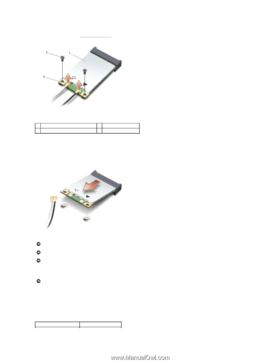
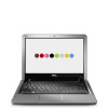
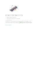
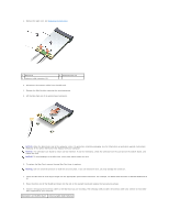
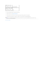
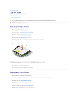
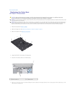
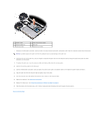
2. Remove the palm rest. See Replacing the Palm Rest. 1 Mini-Card 3 antenna cable connector (2) 2 securing screw (2) 3. Disconnect the antenna cables from the Mini-Card. 4. Release the Mini-Card by removing the securing screws. 5. Lift the Mini-Card out of its system board connector. NOTICE: When the Mini-Card is not in the computer, store it in protective antistatic packaging. See the information on protection against electrostatic discharge in the safety information that shipped with your computer. NOTICE: The connectors are keyed to ensure correct insertion. If you feel resistance, check the connectors on the card and on the system board, and realign the card. NOTICE: To avoid damage to the Mini-Card, never place cables under the card. 6. To replace the Mini-Card, remove the new Mini-Card from its packing. NOTICE: Use firm and even pressure to slide the card into place. If you use excessive force, you may damage the connector. 7. Insert the Mini-Card at a 45-degree angle into the appropriate system board connector. For example, the WLAN card connector is labeled WLAN and so on. 8. Press the other end of the WLAN card down into the slot on the system board and replace the two securing screws. 9. Connect the appropriate antenna cables to the Mini-Card you are installing. The following table provides the antenna cable color scheme for each MiniCard supported by your computer. Connectors on the Mini-Card Antenna Cable Color Scheme
-
 1
1 -
2
-
3
-
4
-
5
-
6
-
7
-
8
-
9
-
10
-
11
-
12
-
13
-
14
-
15
-
16
-
17
-
18
-
19
-
20
-
21
-
 22
22 -
 23
23 -
 24
24 -
 25
25 -
 26
26 -
 27
27 -
 28
28 -
 29
29 -
 30
30 -
 31
31 -
 32
32 -
33
-
34
-
35
-
36
-
37
-
38
 |
 |