Dell Inspiron Mini 12 1210 Inspiron Mini 12 Service Manual - Page 14
Replacing the Display
 |
View all Dell Inspiron Mini 12 1210 manuals
Add to My Manuals
Save this manual to your list of manuals |
Page 14 highlights
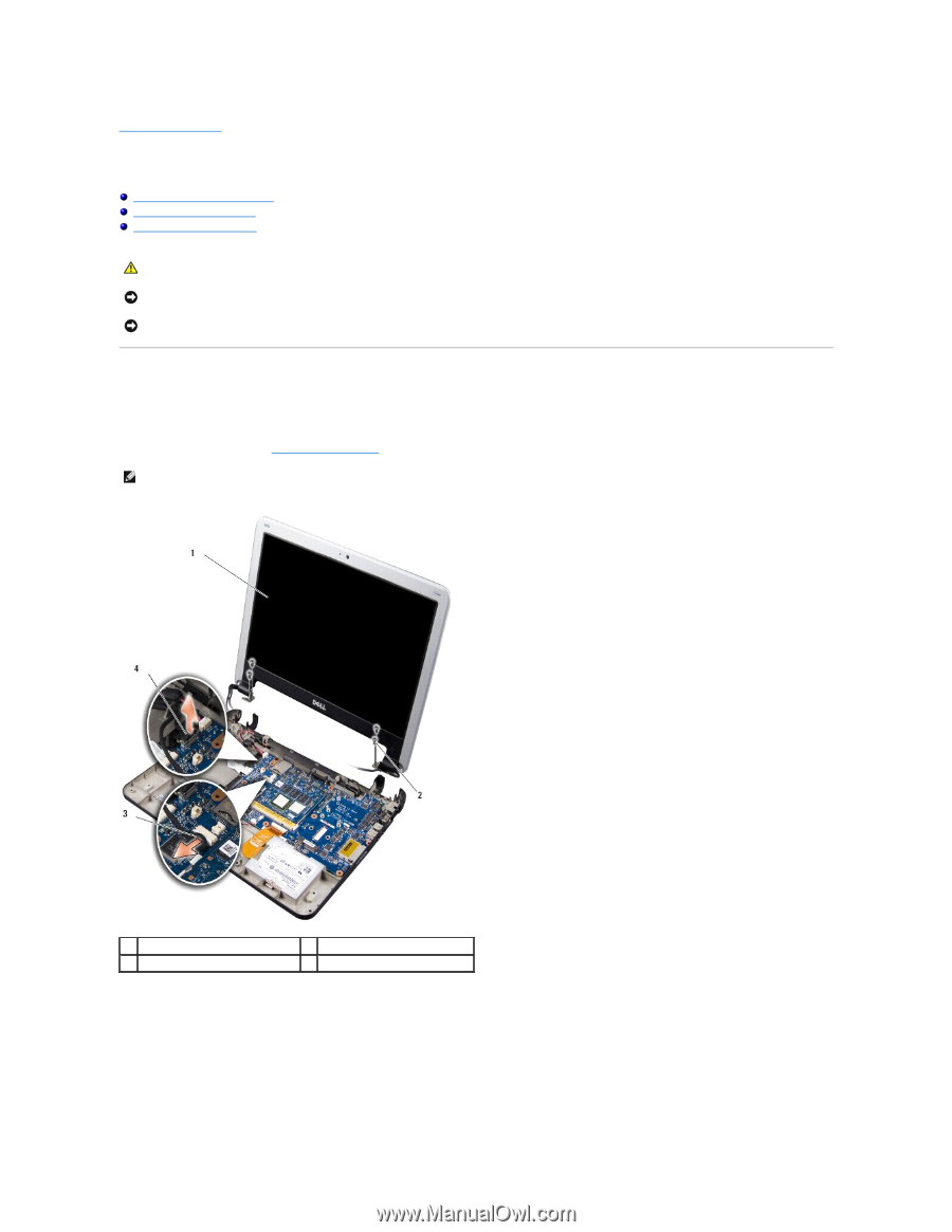
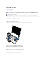
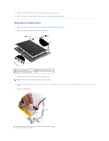
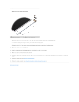
Back to Contents Page Replacing the Display Dell™ Inspiron™ 1210 Service Manual Replacing the Display Assembly Replacing the Display Bezel Replacing the Display Panel CAUTION: Before working inside your computer, read the safety information that shipped with your computer. For additional safety best practices information, see the Regulatory Compliance Homepage at www.dell.com/regulatory_compliance. NOTICE: To avoid electrostatic discharge, ground yourself by using a wrist grounding strap or by periodically touching an unpainted metal surface (such as a connector on the back of the computer). NOTICE: To help prevent damage to the system board, you must remove the battery from the battery bay before you begin working inside the computer. Replacing the Display Assembly 1. Follow the instructions in "Before You Begin" on page 9. 2. Remove the palm rest. See Replacing the Palm Rest. NOTE: Note how the display cable and the 2-in-1 camera and LVDS cable have been connected on the system board. 1 display 3 2-in-1 cable: camera end 2 M2.5 x 3-mm screws (4) 4 2-in-1 cable: LVDS end 3. Pull the display cable tab to disconnect the display cable from the system board connector. 4. Disconnect the 2-in-1 camera and LVDS cable from the system board connector. 5. Remove the four M2.5 x 3-mm screws from the display hinges. 6. Lift and remove the display assembly from the computer base.
-
 1
1 -
2
-
3
-
4
-
5
-
6
-
7
-
8
-
 9
9 -
 10
10 -
 11
11 -
 12
12 -
 13
13 -
 14
14 -
 15
15 -
 16
16 -
 17
17 -
 18
18 -
 19
19 -
20
-
21
-
22
-
23
-
24
-
25
-
26
-
27
-
28
-
29
-
30
-
31
-
32
-
33
-
34
-
35
-
36
-
37
-
38
 |
 |